|
|
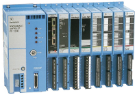
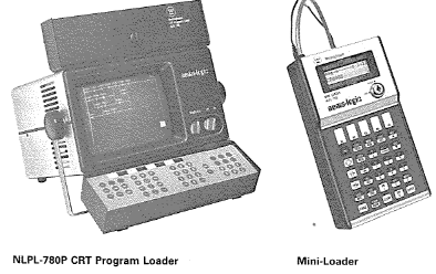
WestinghouseNuma-Logic PC1100 / 1200 / 1250 Family The Numa-Logic PC1100 was a small (originally only 128 digital and 16 analog I/O supported) PLC developed by Westinghouse in the mid 1980's. It was designed to use the same programming methods as the earlier PC900 and PC700 processors and, in fact, the programs were portable between all three classes of machine as long as the program did not exceed a limit imposed by that processor. An example of a limit would be attempting to load a program that used more memory, I/O or functions than were physically available in the smaller machine. This PC1100 processor could be programmed in a variety of ways including using a dedicated CRT programming console, a small "Mini-Loader" or an IBM-compatible MS-DOS personal computer.
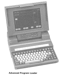
The CRT (NLPL-780) would support printing to an RS-232 serial printer and would support connection to an NLT-783 STR-LINK cassette tape storage system. The Mini-Loader (NLPL-789) offered neither option, but one version (NLPL-789-10-2) did include 1/8" (mini) audio jacks that could be connected to a conventional audio tape recorder to both store and retrieve programs. Note that the audio recording made with the Mini-Loader could not be used by the STR-LINK or vice versa. Westinghouse offered the Advanced Program Loader (APL) in the form of packaged solutions made up of either Compaq or IBM PCs, a suitable RS-232 cable (NLC-6PL: 25-pin or NLC-5PL: 9-pin version) as well as MS-DOS compatible software. Several versions of software were available including NLSW-783, NLSW-783U (included off-line utilities) and NLSW-784 (included ability to document program). The somewhat ground-breaking choice of using a personal computer as a program loader allowed several advanced functionality features to be added over time since the underlying loader was, in fact, a computer. This allowed third party applications to be developed independently from the Westinghouse Numa-Logic factory. For example, an add-on package called "Westinghouse Help Outline" (WHO) or more typically "Online Utilities" was made available as a terminate and stay resident (TSR) program. This TSR program would link with the NLSW-78x program to provide additional functionality. For example, WHO included such additional functionality as a telephone dialer (allow program loader access to a remote PLC connected to an auto-answer modem), advanced PID loop tuning, remote keyswitch control, remote networking using either the PC1100 LAN or via Westnet II Data Highway as well as on-line cross-referencing of used special function and available coils. All Westinghouse program loaders were programmed in 8088 assembly language and were surprisingly responsive (0.2 sec screen refresh), even using the standard 9600 bps link between the IBM PC RS-232 port and the RS-232 port on the PC1100/1200/1250 and recognizing that the underlying computer was typically running on a 4.77 MHz 16-bit internal / 8-bit external CPU. Later Westinghouse offered Toshiba "clam-shell" computers including the T5100 (shown in APL photo above) and the T3200SXC. Both of these computers used the faster 32-bit 80386 (T3200SXC used the 32-bit internal / 16-bit external 80386SX) processors. The latter was the first clam-shell computer with a color screen (VGA 640x480). Later versions of PLCs using the same form factor and I/O as the PC1100 included the more capable and powerful PC1200 and PC1250 processors. In particular, the PC1250 expanded the capabilities (512 digital plus 256 analog I/O) of the family well into the mid-range of PLCs for that time. The PC1100 used 3 standard AA batteries to maintain battery backed up RAM. The advertised life was 3 months with power off and 1 year with power on. The PC1200/1250 used one 3.5 V AA lithium battery. The lithium battery offered substantially longer battery life at 1 year with power off and 5 years with power on. Refer to the PC1100/1200/1250 Systems Manual1 below for more details on this processor family. Note that the Appendix D - New Special Functions only applies to certain PC1200/1250 systems manufactured after 1990. Units built prior to that date did not include these functions. Also, even if some special functions were available, not all functions were built into each processor. Westinghouse sold different versions of each PLC, each having differing amounts of memory and available special functions. PC1100/1200/1250 Systems Manual1
To keep the file download sizes below 4 MB each, Section 5 - Special Functions has been divided into three parts.
Refer to the list below of special functions to locate the page number within either Section 5 or Appendix D where
that particular special function is described in more detail. Note that the page numbering for Appendix D also
started with the number 5, so refer to the column "Section" to know whether that particular special function is
described in Section 5 or in Appendix D.
1 A subset of these functions were available on the older PC700 and PC900 programmable controllers. Return to Numa-Logic page. |
Copyright Loucks Engineering Consultants, LLC 2025
|