- Welcome to LEC Forum.

Recent posts
#11
3-Phase Power / Induction Motor Theory
Last post by Dave Loucks - January 15, 2018, 02:00:12 PMNot sure how helpful this will be, but I presented a talk on how an induction motor operates. Covers some basic rules about Faraday's Law, Lorenz Forces and just in general how you convert electrical current into motion.
HTH
HTH
#12
Modbus / Re: Modbus MINT - 02 Illegal A...
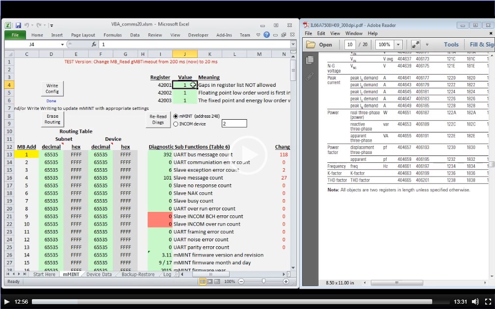
Last post by Dave Loucks - September 01, 2017, 11:39:41 AMHave you attempted to read what should be a valid register and you get the Modbus Exception Code 02 (Illegal Address) or 03 (Illegal Data Value)?
Two fixes:
Click on the image below to view a video explaining this problem with the mMINT and how to fix it (just set 42001 to 0 and make sure you start reading registers at a proper "boundary").
Two fixes:
- Write a 0 to 42001
Writing a zero to this register relaxes the error checking on the mMINT such that if you read a block of registers and one or more of those registers within that block are not supported by the connected device at that address, the mMINT will "zero fill" the response and not send a 02 exception
- Extend the length of block read to include prior registers
For example, attempting to read frequency (406197) alone on a DT1150, even if the 42001 register is set to zero can result in an 02 exception. The fix is to read the prior register 406195 [3-phase apparent power factor] and frequency 406197 as a complete range. For the PM3, that trick doesn't work and you need to back up to start reading at register 406187. Note that for this trick to work in either case, 42001 must also be set to 0. Also, the starting register for this block depends on the device! While starting at 406195 works for the DT1150, to read frequency on the PM3 you must start by reading 406187 and reading the 12 subsequent register pairs all the way to 406198 to pick up the last register of the 32-bit register pair for frequency (406197/406198).
Click on the image below to view a video explaining this problem with the mMINT and how to fix it (just set 42001 to 0 and make sure you start reading registers at a proper "boundary").
#13
Video Tutorials / Directory
Last post by Dave Loucks - June 06, 2017, 09:54:02 AMThese videos are mostly throughout this website. I've just copied them here to a single page for convenience.
| LTSPICE simulation export, resampling and decimation tutorial | https://pps2.com/v/s/1/ltsd.php | |
| Low Voltage Underground Utility Networks | https://pps2.com/v/s/1/nwp.php | |
| Ethernet Networks | https://pps2.com/v/s/1/etht.php | |
| Using Excel to Display Waveforms and Phasor Diagrams | https://pps2.com/v/s/1/opd.php | |
| Using Excel to Display Three-Phase Phasor Diagrams From X-Y Data | https://pps2.com/v/s/1/tpd.php | |
| SFTP Connection to PXMP Meter | https://pps2.com/v/s/1/occn1.php | |
| Using Excel to Generate and Display 3-Phase Harmonics | https://pps2.com/v/s/1/3h.php | |
| Adding the Analysis Tool-Pack to Excel | https://pps2.com/v/s/1/atp.php | |
| Calculating, Displaying and Normalizing FFT Collected From Multiple Devices | https://pps2.com/v/s/1/ceifft.php | |
| Measuring Harmonic Attenuation Using Programmable Phase-Shifted Transformers | https://pps2.com/v/s/1/hmtc.php | |
| Performing Arbitrary Math Functions Within COMTRADE Excel Importer Program | https://pps2.com/v/s/1/cei_math.php | |
| Comparison of Performance Using Zone Selective Interlocking (ZSI) Versus Arcflash Reduction Maintenance System (ARMS) | https://pps2.com/v/s/1/zsi_arms.php | |
| Understanding Differential Relay and CT Matching | https://pps2.com/v/s/1/diff_relay.php | |
| Using the COMTRADE Excel Importer to Determine RMS Values | https://pps2.com/v/s/1/cei_rms.php | |
| Understanding Security When Connecting to a Java Enabled Power Xpert Meter | https://pps2.com/v/s/1/pxmv.php | |
| Harmonic Summation and Cancellation (Phase and Ground) | https://pps2.com/v/1/hmc.php | |
| LTSPICE Quickstart Tutorials Part 1: | https://pps2.com/v/s/1/lts.php | |
| LTSPICE Quickstart Tutorials Part 2: | https://pps2.com/v/s/1/ltsb.php | |
| LTSPICE Quickstart Tutorials Part 3: | https://pps2.com/v/s/1/ltss.php | |
| Power Systems Rule of Thumb (Recording of Instructor Led Class) | https://pps2.com/v/s/1/yg_1.php | |
| (New Version) Power Systems Rule of Thumb (Recording of Instructor Led Class) | https://pps2.com/v/s/1/yg_1a.php | |
| Using Excel to Create Harmonic Trend Viewer for PXM4/6/8K Meters | https://pps2.com/v/1/htv.php | |
| Comparing Fault Current Calculations using "Z Method" Versus the "R+jX Method" | https://pps2.com/v/1/ZvRX.php | |
| Designing Higher Efficiency Mission Critical Power Systems | https://pps2.com/v/s/1/yg_4.php | |
| (New Version) Designing Higher Efficiency Mission Critical Power Systems | https://pps2.com/v/s/1/yg_4a.php | |
| Power System Load Flow and Power Factor Correction Calculations (Recording of Instructor Led Class) | https://pps2.com/v/s/1/yg_3.php | |
| (New Version) Power System Load Flow and Power Factor Correction Calculations (Recording of Instructor Led Class) | https://pps2.com/v/s/1/yg_3a.php | |
| Power System Protection and Coordination (Recording of Instructor Led Class) | https://pps2.com/v/s/1/yg_2.php | |
| (New Version) Power System Protection and Coordination (Recording of Instructor Led Class) | https://pps2.com/v/s/1/yg_2a.php | |
| Predicting, Measuring and Abating Transients on Medium Voltage Systems with Vacuum Switching | https://pps2.com/v/1/cp.php | |
| Modbus MINT Programmer Tutorial | https://pps2.com/v/1/mmint08.php | |
| Modbus MINT Programmer Cloud Backup and Restore | https://pps2.com/v/1/br.php | |
| Modbus MINT Programmer Issuing Control Commands to INCOM Device | https://pps2.com/v/1/control.php | |
| Creating PXG900 Offline Configuration File | https://pps2.com/v/s/1/sstd0.php | |
| Differential Ground Fault Sensing | https://pps2.com/v/1/dgfs.php |
#14
Legacy Motor Control / Westinghouse Advantage MCC
Last post by Dave Loucks - April 20, 2017, 02:21:49 PMThe Advantage MCC was introduced in 1991 and was Westinghouse's first networked motor control.
I wrote a paper on this way back in 1993 entitled "Low-voltage motor control centers utilizing microprocessor technology". See http://ieeexplore.ieee.org/document/231982/
Download the Instruction Booklet IB 8922-1 attached below.
I wrote a paper on this way back in 1993 entitled "Low-voltage motor control centers utilizing microprocessor technology". See http://ieeexplore.ieee.org/document/231982/
Download the Instruction Booklet IB 8922-1 attached below.
#15
Legacy Motor Control / Westinghouse Type W MCC
Last post by Dave Loucks - April 20, 2017, 01:55:24 PMLegacy Westinghouse MCC that was available from roughly 1965 to 1979
Download the instruction book IB12-129 dated July 1978 below.
You can learn more about vintage Westinghouse products (and parts for those products) at http://www.eaton.com/ecm/groups/public/@pub/@electrical/documents/content/ca08100014e.pdf
Download the instruction book IB12-129 dated July 1978 below.
You can learn more about vintage Westinghouse products (and parts for those products) at http://www.eaton.com/ecm/groups/public/@pub/@electrical/documents/content/ca08100014e.pdf
#16
Numa Logic Programmable Controllers / PC700/900/1500/1700 I/O Module...
Last post by Dave Loucks - February 24, 2017, 04:59:23 PMAs I get around to it, I'll scan and add more cards. If you need an instruction booklet for an I/O module that isn't listed here, let me know (dgloucks at gmail dot com)
- NL-740
2-channel, 12-bit isolated, differential input analog input module - NL-742
8-channel, 10 bit singled ended input analog input module - NL-743
16-bit TTL register input module - NL-744
8 or 16 multiplexed 16-bit TTL register input module - NL-750
2 channel, unipolar 12 bit analog output - NL-751
4-channel, 11 bit (10 bits + 1 sign bit) analog (voltage) output - NL-752
4-channel, 10 bits, analog (current) output - NL-753
16-bit TTL register output module - NL-753
8 or 16-channel multiplexed TTL register output module
#17
3-Phase Power / Zone Selective Interlocking an...
Last post by Dave Loucks - February 06, 2017, 12:39:50 PMArticle 240.87 in the NEC mentions that ZSI and something called "energy reducing maintenance switching with local status indicator" are two ways of meeting the requirements of this article.
What is ZSI? How is Eaton's version of the "energy reducing maintenance switching" (called ARMS) different from other vendor's versions?
Click on the image below to view a screencast of me presenting the contents in the attached PPT file below.
What is ZSI? How is Eaton's version of the "energy reducing maintenance switching" (called ARMS) different from other vendor's versions?
Click on the image below to view a screencast of me presenting the contents in the attached PPT file below.
#18
3-Phase Power / Differential Relaying and CT E...
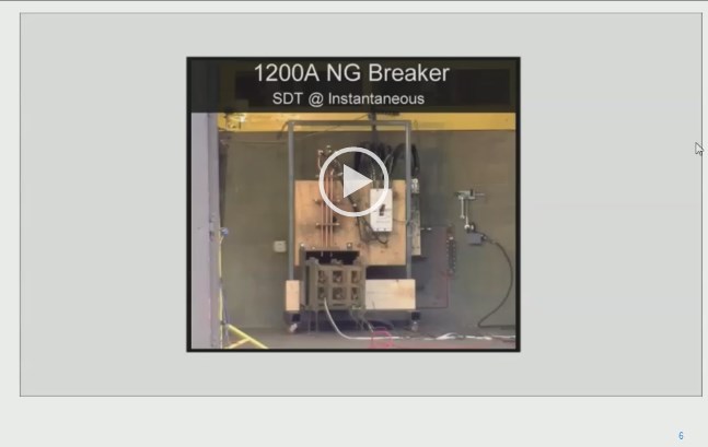
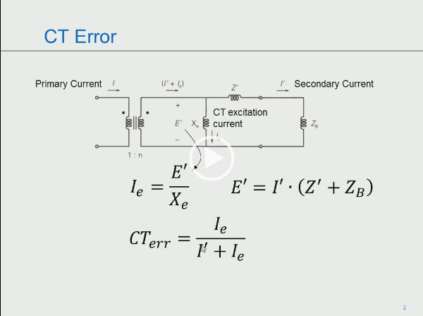
Last post by Dave Loucks - February 06, 2017, 11:11:34 AMArticle 240.87 in the National Electrical Code describes using differential protection as one of the options to use if you have a breaker rated 1200 A or higher. But just what is differential protection and why should or shouldn't be used?
This presentation gives an overview of how differential relaying operates and includes a discussion of CT accuracy and how high resistance loads (e.g. long CT conductors, small wire gauge CT conductors or high impedance loads) affect differential relaying accuracy.
Click on the image below to view a screencast of me presenting the contents in the attached PPT file below.
#19
3-Phase Power / Conductor Temperature Ratings
Last post by Dave Loucks - January 10, 2017, 02:52:05 PMConductors and bus generate heat when current flows through them. How much heat? That depends on the conductor size, the application and many other factors.
For electrical equipment, such as switchgear, switchboards, motor control centers and panel boards, the manufacturer has received certification from UL that at rated current the bus, terminals, connection points and lugs are below the maximum temperature rating permitted by UL.
But what if you want to operate the equipment at an even cooler temperature than this maximum allowable temperature? How much would you need to reduce the current to reduce the temperature?
That's a tricky question because the temperature of equipment likely isn't proportional to the power dissipated. Cooling plays a factor and that cooling too is non-linear with temperature.
Can we at least estimate changes in temperature based on changes in current flow?
One place to start as a first pass approximation is IEEE 399-1997 (Brown Book) where in section 13.4.1, equation 13-5, an "adjustment factor" is calculated for when you want to change either the conductor temperature rating or the ambient temperature:
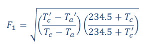
Where:
I'm assuming copper conductors here. You'd use equation 13-6 if you wanted aluminum conductors (just change 234.5 to 228.1 both times).
In our example:
Tc = 105oC (40 + 65)
Tc' = 70oC (40 + 30)
Ta = 40
Ta' = 40 (no change)
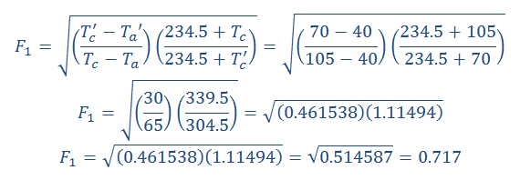
So, this would imply that if you ran the conductor at no higher than 72% of its rated capacity (or better, 71%) the conductor temperature would not rise more than 30oC above a 40oC ambient.
Consider this only back of the envelope calculations since it could be better (there is might be better air circulation) or worse (you might have harmonics which will induce eddy current heating)
Here's a calculator that automates this math:
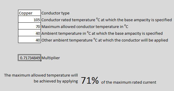
You can click on the image above to download, or select "conductor_temp_rerating.xlsx" from below.
For electrical equipment, such as switchgear, switchboards, motor control centers and panel boards, the manufacturer has received certification from UL that at rated current the bus, terminals, connection points and lugs are below the maximum temperature rating permitted by UL.
But what if you want to operate the equipment at an even cooler temperature than this maximum allowable temperature? How much would you need to reduce the current to reduce the temperature?
That's a tricky question because the temperature of equipment likely isn't proportional to the power dissipated. Cooling plays a factor and that cooling too is non-linear with temperature.
Can we at least estimate changes in temperature based on changes in current flow?
One place to start as a first pass approximation is IEEE 399-1997 (Brown Book) where in section 13.4.1, equation 13-5, an "adjustment factor" is calculated for when you want to change either the conductor temperature rating or the ambient temperature:
Where:
| Tc | Conductor rated temperature in oC at which the base ampacity is specified | |
| Tc' | Maximum allowed conductor temperature in oC | |
| Ta | Ambient temperature in oC at which the base ampacity is specified | |
| Ta' | Other ambient temperature oC at which the conductor will be applied |
I'm assuming copper conductors here. You'd use equation 13-6 if you wanted aluminum conductors (just change 234.5 to 228.1 both times).
In our example:
Tc = 105oC (40 + 65)
Tc' = 70oC (40 + 30)
Ta = 40
Ta' = 40 (no change)
So, this would imply that if you ran the conductor at no higher than 72% of its rated capacity (or better, 71%) the conductor temperature would not rise more than 30oC above a 40oC ambient.
Consider this only back of the envelope calculations since it could be better (there is might be better air circulation) or worse (you might have harmonics which will induce eddy current heating)
Here's a calculator that automates this math:
You can click on the image above to download, or select "conductor_temp_rerating.xlsx" from below.
#20
Power Xpert Gateway / PXG Configuration
Last post by Dave Loucks - January 03, 2017, 03:02:28 PMWhile you can certainly just plug in a browser and configure a PXG900, there are a couple of things you should know to make things go more smoothly.
If you are using a Windows PC and have admin rights, you might want to consider using themicromini-USB connection on the front of the PXG900 (formerly a type A USB connection on the "E" series gateways). The default address for that port is always 192.168.200.101. The disadvantage is you will need to load a USB driver onto your computer (instructions) and you will need Admin rights to allow that.
If instead you use the Ethernet port, you should know that this port supports Zero Config and that means that the default IP address can move around! While the default IP address on the Ethernet port following a factory reset is https://169.254.1.1 (or http://169.254.1.1), that will only be the case if nothing else is "heard" when the PXG boots. Best bet is to make sure nothing is connected to the network 1 port during a factory reset.
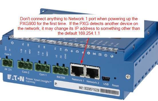
Once you are able to connect with the gateway and have changed the IP address to a new fixed (static) value, zero config is disabled and you'll have a good known fixed IP address for the PXG.
But why mess around with all this? Did you know there was an "low touch" loading method for the PXG900? (actually also works on the "E" series, i.e. PXG200E, 400E, 600E, and 800E gateways with latest firmware too). You'll still need admin rights to both load this program and load the USB driver (which the installer does automatically).
The "Configuration Automator" program (link at end of this topic) removes a lot of the complexity when you are tasked with loading the PXG configuration. It does this by semi-automatically installing an XML file that contains the settings you wish to install.
This XML file can be created a number of ways, but perhaps the easiest is to use the PXG offline configuration spreadsheet.
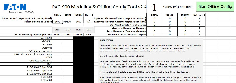
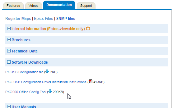
You can download a copy of the offline configurator and try it yourself (if this deep link has expired -- which it might when the program is updated -- just navigate to https://eaton.com/pxg and select "PXG900 Offline Config Tool" under the "Software Downloads" section in the "Documentation" tab.
Here are some screencast videos that explain how these programs work:
If you are using a Windows PC and have admin rights, you might want to consider using the
If instead you use the Ethernet port, you should know that this port supports Zero Config and that means that the default IP address can move around! While the default IP address on the Ethernet port following a factory reset is https://169.254.1.1 (or http://169.254.1.1), that will only be the case if nothing else is "heard" when the PXG boots. Best bet is to make sure nothing is connected to the network 1 port during a factory reset.
Once you are able to connect with the gateway and have changed the IP address to a new fixed (static) value, zero config is disabled and you'll have a good known fixed IP address for the PXG.
But why mess around with all this? Did you know there was an "low touch" loading method for the PXG900? (actually also works on the "E" series, i.e. PXG200E, 400E, 600E, and 800E gateways with latest firmware too). You'll still need admin rights to both load this program and load the USB driver (which the installer does automatically).
The "Configuration Automator" program (link at end of this topic) removes a lot of the complexity when you are tasked with loading the PXG configuration. It does this by semi-automatically installing an XML file that contains the settings you wish to install.
This XML file can be created a number of ways, but perhaps the easiest is to use the PXG offline configuration spreadsheet.
You can download a copy of the offline configurator and try it yourself (if this deep link has expired -- which it might when the program is updated -- just navigate to https://eaton.com/pxg and select "PXG900 Offline Config Tool" under the "Software Downloads" section in the "Documentation" tab.
Here are some screencast videos that explain how these programs work:
- Configuration Uploading Automator (Low-Touch Loader)
Part 1: Software Installation (Video 2:30, PDF instructions attached below)
Part 2: Using the Configuration Uploading Automator (Video 4:49 PDF instructions attached below)
- PXG 900 Offline Configurator (XML file creator)
Part 0: Creating PXG XML file for uploading (Video 3:53 PDF instructions attached below)