- Welcome to LEC Forum.

Recent posts
#1
INCOM / IMPACC / DT1150 Configuration Tool
Last post by Dave Loucks - July 21, 2022, 11:53:53 PMAs users of the Westinghouse/Cutler-Hammer/Eaton Digitrip 1150 (DT1150) know, there is no tool available to edit or backup/restore a DT1150 trip unit.
While developing the code to configure this product using the Eaton Device Configuration Management Software (DCMS, or internally to Eaton known as "No Touch / Low Touch Loader or NTLT), we needed a configuration file to save in the cloud for this product.
Since none existed, we developed our own based on a simple multi-column CSV (comma separated values) format. Since the file was a bit cryptic to interpret, we also created some macros within Excel VBA that would convert the file into something more readable.
Click on the link below to download the file and an example DT1150 configuration file.
https://pps2.com/smf/index.php?action=dlattach;topic=238.0;attach=136
#2
Motor Control / C440
Last post by Dave Loucks - May 09, 2019, 04:00:10 PMWent looking for instructions for the Modbus RTU add-in module for the C440 overload relay and had trouble finding it. So am putting a copy below.
#3
Modbus / Decoding 32- and 64-bit fixed ...
Last post by Dave Loucks - November 12, 2018, 10:25:21 AMWhile the published Modbus standard explains the bit/byte order of 16-bit registers, it doesn't include any instructions for how to deal with 32 or 64-bit registers. That is left up to the vendors using the Modbus protocol. Here is how the mMINT handles them.
Example:
Read 32-bit Product ID Modbus Register pair (406255/406256)
Value = (3171) + (128*655361)
Value = (3171) + (8388608)
Value = 8391779 (800C6316)
For 64-bit values, the process is similar.
Example:
Read 64-bit Real-Energy-Forward Modbus Register 4-register group (406305-406308)
Value = 0 +... + 0 + 316 * 7.206 x 1016
Value = 2.1617 x 10¹⁷
Example:
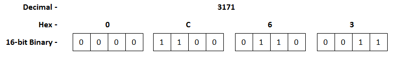
Read 32-bit Product ID Modbus Register pair (406255/406256)
- Remove the "40" and subtract 1 from lowest register number to find "wire" starting address:
406255 -> 6254 - Convert to hex:
625410 -> 186E16 - Place in proper location of Modbus message
Starting Address Low Byte 6E Starting Address High Byte 18
|
|
- 406255 = 317110 (0C6316)
- 406256 = 12810 (8016)
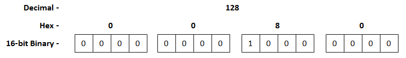
Value = (3171) + (128*655361)
Value = (3171) + (8388608)
Value = 8391779 (800C6316)
For 64-bit values, the process is similar.
Example:
Read 64-bit Real-Energy-Forward Modbus Register 4-register group (406305-406308)
- Starting with the first register in the list, remove the "40" from the beginning of the register number then subtract 1 from what remains:
406305 -> 6304 - Convert to hex:
630410 -> 18A016 - Place in proper location of Modbus message
Starting Address Low Byte A0 Starting Address High Byte 18
|
|
- 406305 = 0
- 406306 = 0
- 406307 = 0
- 406308 = 3
| Register Value (High)(406305) | 00 * 2561 |
| Register Value (Low)(406305) | 00 * 2560 |
| Register Value (High)(406306) | 00 * 2563 |
| Register Value (Low)(406306) | 00 * 2562 |
| Register Value (High)(406307) | 00 * 2565 |
| Register Value (Low)(406307) | 00 * 2564 |
| Register Value (High)(406308) | 03 * 2567 |
| Register Value (Low)(406308) | 00 * 2566 |
Value = 2.1617 x 10¹⁷
#4
Trip Units / Modbus Control of ARMS mode (A...
Last post by Dave Loucks - July 10, 2018, 01:43:53 PMThe DT1150 electronic trip unit supports both reading and writing (changing) the status of the ARMS mode. The ARMS status is held in message 59 of the INCOM 3 C 9 "Read Setpoints Buffer".
From page 49 of the latest IL17384 (Part C - Protective Relays and Trip Units INCOM/IMPACC protocol guide)
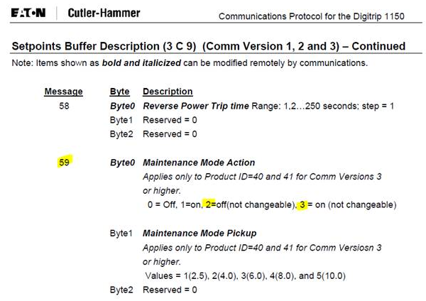
Note: "not changeable" means the mode was set by the switch and software cannot change the state unless the switch is off.
Access the DT1150 Setpoints Buffer - Maintenance Mode status using Modbus messages:
Setpoints Buffer Description command 3 C 9 is an Incom command that can be used to poll Maintenance mode status.
Message 59 of the response data indicates Maintenance Mode Status.
Using the Modbus MINT this setting change read or changed by sending different Modbus RTU message.
The screenshots shown below are based on the ComTestPro Modbus utility available for free from http://www.baseblock.com/PRODUCTS/comtestpro.htm
On the Modbus master side:
Using func code 16
Write C3BEh to 6000h
Write 9002h to 6001hM
Note the 2 in 9002 is the Incom address
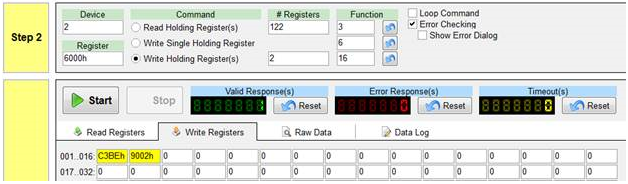
Then with function code 3 read 122 registers from 6000h
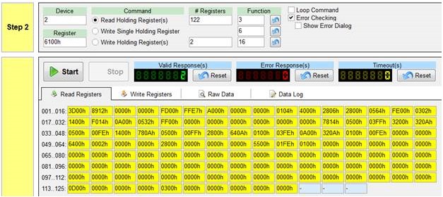
The 212th byte after the Modbus message byte count [F4h] is byte 0 of Message 59 which is Maintenance mode status.
Byte 212 highlighted below indicates changing from 02h to 03h, confirming toggle of Maintenance Mode.
Maintenance Mode is OFF
WRITE to 6000h/6001h
Baseblock ComTest Pro for Modbus Devices, Version: 2.0.5.1
Clear Log : Start > 11/23/2015 11:07:43 AM
11:07:56.517: Com1, Baud Rate: 9600, Data Bits: 8 Bits, Parity: None, Stop Bits: 1 Stop Bit
11:07:56.517: Echoback: Off, RTS Control: Off, Transmit Delay: 5 ms, Response Delay: 3000 ms
11:07:56.520: Write Holding Register(s)
11:07:56.520: Device Address: 02h, Register: 6000h, Number of Registers: 2
11:07:56.521: |-> Write Register: 6000h, Number of Registers : 2
11:07:56.528: -> [02h] [10h] [60h] [00h] [00h] [02h] [04h] [C3h] [BEh] [90h] [02h] [E5h] [48h]
11:07:56.567: <- [02h] [10h] [60h] [00h] [00h] [02h] [5Fh] [FBh]
READ from 6100h
11:08:59.881: Com1, Baud Rate: 9600, Data Bits: 8 Bits, Parity: None, Stop Bits: 1 Stop Bit
11:08:59.882: Echoback: Off, RTS Control: Off, Transmit Delay: 5 ms, Response Delay: 3000 ms
11:08:59.885: Read Holding Register(s)
11:08:59.885: Device Address: 02h, Register: 6100h, Number of Registers: 122
11:08:59.885: |-> Read Register: 6100h, Number of Registers : 122
11:08:59.895: -> [02h] [03h] [61h] [00h] [00h] [7Ah] [DBh] [E6h]
11:09:00.289: <- [02h] [03h] [F4h] [3Dh] [00h] [89h] [0Ah] [00h] [00h] [00h] [00h] [FDh] [00h] [FFh] [E7h] [A0h] [00h] [00h] [00h] [00h] [00h] [01h] [04h] [D0h] [00h] [28h] [07h] [28h] [00h] [05h] [64h] [FEh] [00h] [03h] [02h] [14h] [00h] [F0h] [14h] [0Ah] [00h] [05h] [32h] [FFh] [00h] [00h] [00h] [00h] [00h] [00h] [00h] [00h] [00h] [00h] [00h] [00h] [00h] [78h] [14h] [05h] [00h] [03h] [FFh] [0Ah] [00h] [32h] [0Ah] [05h] [00h] [00h] [FEh] [14h] [00h] [78h] [0Ah] [05h] [00h] [01h] [FFh] [19h] [00h] [64h] [0Ah] [01h] [00h] [03h] [FEh] [0Ah] [00h] [32h] [0Ah] [01h] [00h] [00h] [FEh] [00h] [00h] [00h] [00h] [64h] [00h] [00h] [02h] [00h] [00h] [00h] [00h] [19h] [00h] [00h] [00h] [00h] [00h] [00h] [00h] [55h] [00h] [01h] [FEh] [00h] [00h] [00h] [00h] [00h] [00h] [00h] [00h] [00h] [00h] [00h] [00h] [00h] [00h] [00h] [00h] [00h] [00h] [00h] [00h] [00h] [00h] [00h] [00h] [00h] [00h] [00h] [00h] [00h] [00h] [00h] [00h] [00h] [00h] [00h] [00h] [00h] [00h] [00h] [00h] [00h] [00h] [00h] [00h] [00h] [00h] [00h] [00h] [00h] [00h] [00h] [00h] [00h] [00h] [00h] [00h] [00h] [00h] [00h] [00h] [00h] [00h] [00h] [00h] [00h] [00h] [00h] [00h] [00h] [00h] [00h] [00h] [00h] [00h] [00h] [00h] [00h] [00h] [00h] [00h] [00h] [00h] [00h] [00h] [00h] [00h] [00h] [00h] [00h] [00h] [00h] [00h] [00h] [00h] [00h] [00h] [00h] [00h] [00h] [00h] [00h] [00h] [00h] [00h] [00h] [00h] [00h] [00h] [0Eh] [00h] [00h] [00h] [00h] [00h] [00h] [00h] [02h] [00h] [00h] [00h] [00h] [00h] [00h] [00h] [00h] [00h] [00h] [00h] [79h] [02h]
Note the 02h value in the 59th message. From Maintenance Mode Action field above, 02h is confirmed to be OFF (not changeable). However, what the really means is that the ARMS was switched off by the switch on the trip unit. Since the switch is off, you can override that value in software.
Maintenance Mode is turned ON
WRITE to 6000h/6001h
11:10:19.387: Com1, Baud Rate: 9600, Data Bits: 8 Bits, Parity: None, Stop Bits: 1 Stop Bit
11:10:19.387: Echoback: Off, RTS Control: Off, Transmit Delay: 5 ms, Response Delay: 3000 ms
11:10:19.395: Write Holding Register(s)
11:10:19.400: Device Address: 02h, Register: 6000h, Number of Registers: 2
11:10:19.403: |-> Write Register: 6000h, Number of Registers : 2
11:10:19.412: -> [02h] [10h] [60h] [00h] [00h] [02h] [04h] [C3h] [BEh] [90h] [02h] [E5h] [48h]
11:10:19.451: <- [02h] [10h] [60h] [00h] [00h] [02h] [5Fh] [FBh]
READ from 6100h
11:10:29.813: Com1, Baud Rate: 9600, Data Bits: 8 Bits, Parity: None, Stop Bits: 1 Stop Bit
11:10:29.817: Echoback: Off, RTS Control: Off, Transmit Delay: 5 ms, Response Delay: 3000 ms
11:10:29.823: Read Holding Register(s)
11:10:29.827: Device Address: 02h, Register: 6100h, Number of Registers: 122
11:10:29.831: |-> Read Register: 6100h, Number of Registers : 122
11:10:29.840: -> [02h] [03h] [61h] [00h] [00h] [7Ah] [DBh] [E6h]
11:10:30.232: <- [02h] [03h] [F4h] [3Dh] [00h] [89h] [0Ah] [00h] [00h] [00h] [00h] [FDh] [00h] [FFh] [E7h] [A0h] [00h] [00h] [00h] [00h] [00h] [01h] [04h] [D0h] [00h] [28h] [07h] [28h] [00h] [05h] [64h] [FEh] [00h] [03h] [02h] [14h] [00h] [F0h] [14h] [0Ah] [00h] [05h] [32h] [FFh] [00h] [00h] [00h] [00h] [00h] [00h] [00h] [00h] [00h] [00h] [00h] [00h] [00h] [78h] [14h] [05h] [00h] [03h] [FFh] [0Ah] [00h] [32h] [0Ah] [05h] [00h] [00h] [FEh] [14h] [00h] [78h] [0Ah] [05h] [00h] [01h] [FFh] [19h] [00h] [64h] [0Ah] [01h] [00h] [03h] [FEh] [0Ah] [00h] [32h] [0Ah] [01h] [00h] [00h] [FEh] [00h] [00h] [00h] [00h] [64h] [00h] [00h] [02h] [00h] [00h] [00h] [00h] [19h] [00h] [00h] [00h] [00h] [00h] [00h] [00h] [55h] [00h] [01h] [FEh] [00h] [00h] [00h] [00h] [00h] [00h] [00h] [00h] [00h] [00h] [00h] [00h] [00h] [00h] [00h] [00h] [00h] [00h] [00h] [00h] [00h] [00h] [00h] [00h] [00h] [00h] [00h] [00h] [00h] [00h] [00h] [00h] [00h] [00h] [00h] [00h] [00h] [00h] [00h] [00h] [00h] [00h] [00h] [00h] [00h] [00h] [00h] [00h] [00h] [00h] [00h] [00h] [00h] [00h] [00h] [00h] [00h] [00h] [00h] [00h] [00h] [00h] [00h] [00h] [00h] [00h] [00h] [00h] [00h] [00h] [00h] [00h] [00h] [00h] [00h] [00h] [00h] [00h] [00h] [00h] [00h] [00h] [00h] [00h] [00h] [00h] [00h] [00h] [00h] [00h] [00h] [00h] [00h] [00h] [00h] [00h] [00h] [00h] [00h] [00h] [00h] [00h] [00h] [00h] [00h] [00h] [00h] [00h] [0Eh] [00h] [00h] [00h] [00h] [00h] [00h] [00h] [03h] [00h] [00h] [00h] [00h] [00h] [00h] [00h] [00h] [00h] [00h] [00h] [84h] [C1h]
Since the payload in INCOM messages is 24-bits long, and since Modbus RTU messages have 16-bit registers, the Modbus MINT uses two 16 bit registers (4-bytes) for one INCOM message.
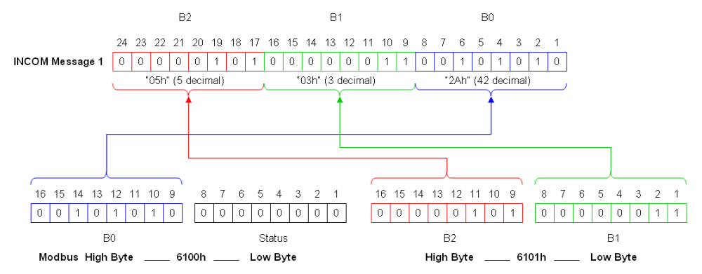
The DT1150 setpoint Buffer is 61 messages (61*4 = 244 [0xF4] bytes long). Note the 03h value in the 59th message indicating that ARMS mode is activated via a switch or contact closer (it would be 01h if it were activated via the communications channel)
Changing this value is much more involved compared to simply reading it since the Modbus MINT requires that each separate INCOM message be sent as a separate Modbus message (and the Setpoint command has 61 separate messages plus a checksum message for 62 total!) See INCOM Pass-Through Messaging via Modbus MINT for more details on how this is done.
From page 49 of the latest IL17384 (Part C - Protective Relays and Trip Units INCOM/IMPACC protocol guide)
Note: "not changeable" means the mode was set by the switch and software cannot change the state unless the switch is off.
Access the DT1150 Setpoints Buffer - Maintenance Mode status using Modbus messages:
Setpoints Buffer Description command 3 C 9 is an Incom command that can be used to poll Maintenance mode status.
Message 59 of the response data indicates Maintenance Mode Status.
Using the Modbus MINT this setting change read or changed by sending different Modbus RTU message.
The screenshots shown below are based on the ComTestPro Modbus utility available for free from http://www.baseblock.com/PRODUCTS/comtestpro.htm
On the Modbus master side:
Using func code 16
Write C3BEh to 6000h
Write 9002h to 6001hM
Note the 2 in 9002 is the Incom address
Then with function code 3 read 122 registers from 6000h
The 212th byte after the Modbus message byte count [F4h] is byte 0 of Message 59 which is Maintenance mode status.
Byte 212 highlighted below indicates changing from 02h to 03h, confirming toggle of Maintenance Mode.
Maintenance Mode is OFF
WRITE to 6000h/6001h
Baseblock ComTest Pro for Modbus Devices, Version: 2.0.5.1
Clear Log : Start > 11/23/2015 11:07:43 AM
11:07:56.517: Com1, Baud Rate: 9600, Data Bits: 8 Bits, Parity: None, Stop Bits: 1 Stop Bit
11:07:56.517: Echoback: Off, RTS Control: Off, Transmit Delay: 5 ms, Response Delay: 3000 ms
11:07:56.520: Write Holding Register(s)
11:07:56.520: Device Address: 02h, Register: 6000h, Number of Registers: 2
11:07:56.521: |-> Write Register: 6000h, Number of Registers : 2
11:07:56.528: -> [02h] [10h] [60h] [00h] [00h] [02h] [04h] [C3h] [BEh] [90h] [02h] [E5h] [48h]
11:07:56.567: <- [02h] [10h] [60h] [00h] [00h] [02h] [5Fh] [FBh]
READ from 6100h
11:08:59.881: Com1, Baud Rate: 9600, Data Bits: 8 Bits, Parity: None, Stop Bits: 1 Stop Bit
11:08:59.882: Echoback: Off, RTS Control: Off, Transmit Delay: 5 ms, Response Delay: 3000 ms
11:08:59.885: Read Holding Register(s)
11:08:59.885: Device Address: 02h, Register: 6100h, Number of Registers: 122
11:08:59.885: |-> Read Register: 6100h, Number of Registers : 122
11:08:59.895: -> [02h] [03h] [61h] [00h] [00h] [7Ah] [DBh] [E6h]
11:09:00.289: <- [02h] [03h] [F4h] [3Dh] [00h] [89h] [0Ah] [00h] [00h] [00h] [00h] [FDh] [00h] [FFh] [E7h] [A0h] [00h] [00h] [00h] [00h] [00h] [01h] [04h] [D0h] [00h] [28h] [07h] [28h] [00h] [05h] [64h] [FEh] [00h] [03h] [02h] [14h] [00h] [F0h] [14h] [0Ah] [00h] [05h] [32h] [FFh] [00h] [00h] [00h] [00h] [00h] [00h] [00h] [00h] [00h] [00h] [00h] [00h] [00h] [78h] [14h] [05h] [00h] [03h] [FFh] [0Ah] [00h] [32h] [0Ah] [05h] [00h] [00h] [FEh] [14h] [00h] [78h] [0Ah] [05h] [00h] [01h] [FFh] [19h] [00h] [64h] [0Ah] [01h] [00h] [03h] [FEh] [0Ah] [00h] [32h] [0Ah] [01h] [00h] [00h] [FEh] [00h] [00h] [00h] [00h] [64h] [00h] [00h] [02h] [00h] [00h] [00h] [00h] [19h] [00h] [00h] [00h] [00h] [00h] [00h] [00h] [55h] [00h] [01h] [FEh] [00h] [00h] [00h] [00h] [00h] [00h] [00h] [00h] [00h] [00h] [00h] [00h] [00h] [00h] [00h] [00h] [00h] [00h] [00h] [00h] [00h] [00h] [00h] [00h] [00h] [00h] [00h] [00h] [00h] [00h] [00h] [00h] [00h] [00h] [00h] [00h] [00h] [00h] [00h] [00h] [00h] [00h] [00h] [00h] [00h] [00h] [00h] [00h] [00h] [00h] [00h] [00h] [00h] [00h] [00h] [00h] [00h] [00h] [00h] [00h] [00h] [00h] [00h] [00h] [00h] [00h] [00h] [00h] [00h] [00h] [00h] [00h] [00h] [00h] [00h] [00h] [00h] [00h] [00h] [00h] [00h] [00h] [00h] [00h] [00h] [00h] [00h] [00h] [00h] [00h] [00h] [00h] [00h] [00h] [00h] [00h] [00h] [00h] [00h] [00h] [00h] [00h] [00h] [00h] [00h] [00h] [00h] [00h] [0Eh] [00h] [00h] [00h] [00h] [00h] [00h] [00h] [02h] [00h] [00h] [00h] [00h] [00h] [00h] [00h] [00h] [00h] [00h] [00h] [79h] [02h]
Note the 02h value in the 59th message. From Maintenance Mode Action field above, 02h is confirmed to be OFF (not changeable). However, what the really means is that the ARMS was switched off by the switch on the trip unit. Since the switch is off, you can override that value in software.
Maintenance Mode is turned ON
WRITE to 6000h/6001h
11:10:19.387: Com1, Baud Rate: 9600, Data Bits: 8 Bits, Parity: None, Stop Bits: 1 Stop Bit
11:10:19.387: Echoback: Off, RTS Control: Off, Transmit Delay: 5 ms, Response Delay: 3000 ms
11:10:19.395: Write Holding Register(s)
11:10:19.400: Device Address: 02h, Register: 6000h, Number of Registers: 2
11:10:19.403: |-> Write Register: 6000h, Number of Registers : 2
11:10:19.412: -> [02h] [10h] [60h] [00h] [00h] [02h] [04h] [C3h] [BEh] [90h] [02h] [E5h] [48h]
11:10:19.451: <- [02h] [10h] [60h] [00h] [00h] [02h] [5Fh] [FBh]
READ from 6100h
11:10:29.813: Com1, Baud Rate: 9600, Data Bits: 8 Bits, Parity: None, Stop Bits: 1 Stop Bit
11:10:29.817: Echoback: Off, RTS Control: Off, Transmit Delay: 5 ms, Response Delay: 3000 ms
11:10:29.823: Read Holding Register(s)
11:10:29.827: Device Address: 02h, Register: 6100h, Number of Registers: 122
11:10:29.831: |-> Read Register: 6100h, Number of Registers : 122
11:10:29.840: -> [02h] [03h] [61h] [00h] [00h] [7Ah] [DBh] [E6h]
11:10:30.232: <- [02h] [03h] [F4h] [3Dh] [00h] [89h] [0Ah] [00h] [00h] [00h] [00h] [FDh] [00h] [FFh] [E7h] [A0h] [00h] [00h] [00h] [00h] [00h] [01h] [04h] [D0h] [00h] [28h] [07h] [28h] [00h] [05h] [64h] [FEh] [00h] [03h] [02h] [14h] [00h] [F0h] [14h] [0Ah] [00h] [05h] [32h] [FFh] [00h] [00h] [00h] [00h] [00h] [00h] [00h] [00h] [00h] [00h] [00h] [00h] [00h] [78h] [14h] [05h] [00h] [03h] [FFh] [0Ah] [00h] [32h] [0Ah] [05h] [00h] [00h] [FEh] [14h] [00h] [78h] [0Ah] [05h] [00h] [01h] [FFh] [19h] [00h] [64h] [0Ah] [01h] [00h] [03h] [FEh] [0Ah] [00h] [32h] [0Ah] [01h] [00h] [00h] [FEh] [00h] [00h] [00h] [00h] [64h] [00h] [00h] [02h] [00h] [00h] [00h] [00h] [19h] [00h] [00h] [00h] [00h] [00h] [00h] [00h] [55h] [00h] [01h] [FEh] [00h] [00h] [00h] [00h] [00h] [00h] [00h] [00h] [00h] [00h] [00h] [00h] [00h] [00h] [00h] [00h] [00h] [00h] [00h] [00h] [00h] [00h] [00h] [00h] [00h] [00h] [00h] [00h] [00h] [00h] [00h] [00h] [00h] [00h] [00h] [00h] [00h] [00h] [00h] [00h] [00h] [00h] [00h] [00h] [00h] [00h] [00h] [00h] [00h] [00h] [00h] [00h] [00h] [00h] [00h] [00h] [00h] [00h] [00h] [00h] [00h] [00h] [00h] [00h] [00h] [00h] [00h] [00h] [00h] [00h] [00h] [00h] [00h] [00h] [00h] [00h] [00h] [00h] [00h] [00h] [00h] [00h] [00h] [00h] [00h] [00h] [00h] [00h] [00h] [00h] [00h] [00h] [00h] [00h] [00h] [00h] [00h] [00h] [00h] [00h] [00h] [00h] [00h] [00h] [00h] [00h] [00h] [00h] [0Eh] [00h] [00h] [00h] [00h] [00h] [00h] [00h] [03h] [00h] [00h] [00h] [00h] [00h] [00h] [00h] [00h] [00h] [00h] [00h] [84h] [C1h]
Since the payload in INCOM messages is 24-bits long, and since Modbus RTU messages have 16-bit registers, the Modbus MINT uses two 16 bit registers (4-bytes) for one INCOM message.
The DT1150 setpoint Buffer is 61 messages (61*4 = 244 [0xF4] bytes long). Note the 03h value in the 59th message indicating that ARMS mode is activated via a switch or contact closer (it would be 01h if it were activated via the communications channel)
Changing this value is much more involved compared to simply reading it since the Modbus MINT requires that each separate INCOM message be sent as a separate Modbus message (and the Setpoint command has 61 separate messages plus a checksum message for 62 total!) See INCOM Pass-Through Messaging via Modbus MINT for more details on how this is done.
#5
3-Phase Power / Re: Power Systems UPS
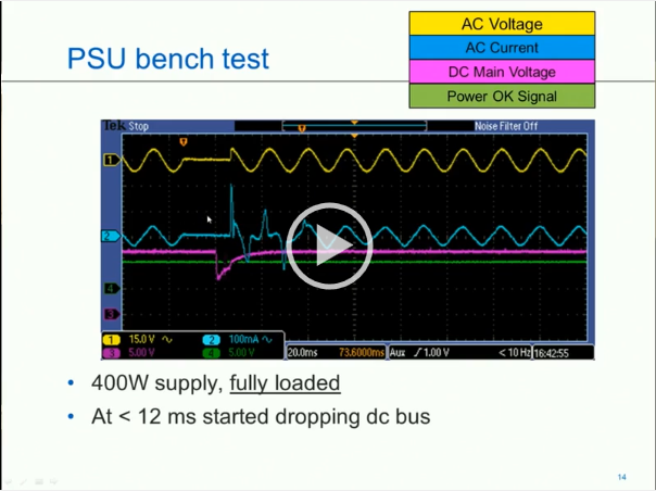
Last post by Dave Loucks - May 15, 2018, 03:23:24 PMHere's an updated video version of me giving this presentation.
With this class I only had about 25 minutes so didn't cover all the material.
Also, you'll notice the audio changing during the presentation. What happened was that my lavalier mic wasn't plugged in completely to my digital recorder and I would get popping or other noise. During those times the audio recorded from that mic was unusable.
So, instead I switched over to the slightly less clear microphone on the computer or as a third backup, the microphone on the video camera recording the presentation.
#6
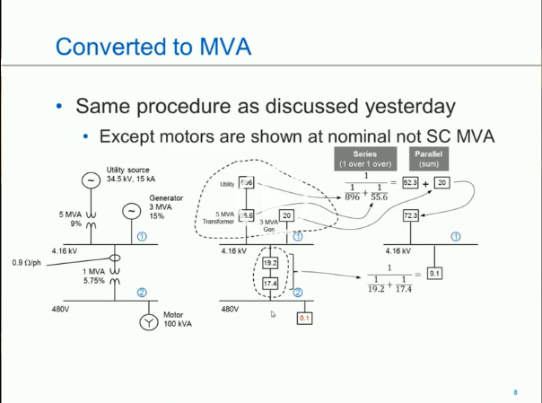
3-Phase Power / Re: Power Systems Load Flow an...
Last post by Dave Loucks - May 15, 2018, 03:14:17 PMAnother update. Click image below to play video of me giving this presentation:
#7
3-Phase Power / Re: Power Systems Protection a...
Last post by Dave Loucks - May 15, 2018, 03:10:04 PMAnother update:
#8
3-Phase Power / Re: Power Systems Rules of Thu...
Last post by Dave Loucks - May 15, 2018, 03:07:22 PMHere's another update on this same material...

#9
Modbus / USB to RS-485 adapter for Comp...
Last post by Dave Loucks - February 15, 2018, 08:14:59 AMSince the mMINT communicates on Modbus using RS-485 and since most computers and laptops don't have an RS-485 port you might ask "how do I talk to the mMINT?"
Here's an article that discusses one very inexpensive method.
Here's an article that discusses one very inexpensive method.
#10
Modbus / Low cost 485 adapter for your ...
Last post by Dave Loucks - February 12, 2018, 05:05:57 PMModern computers are no longer supplied with serial ports (other than Ethernet and USB), and even back when they did they were supplied, they were RS-232. Even then to get an RS-485 connection, you'll need a converter.
There are ton of high quality converters from companies like B&B Electronics, but if all you want is an inexpensive 2-wire USB to RS-485 converter, this one has been tested and works fine with the VBA_COMMS program.
Don't expect it to withstand the rigors of an industrial environment, but if you are looking for a low cost way of programming the Modbus MINT, this is a great choice (at least in February 2018 when this article was written).
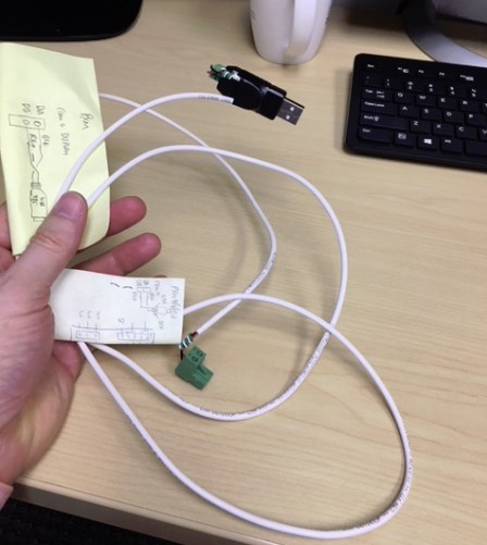
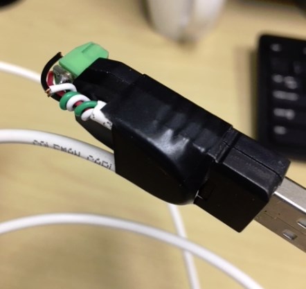
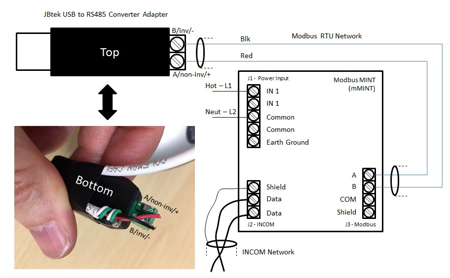
Here's a wiring diagram showing how the JBTech USB to RS485 adapter would be wired to the Modbus MINT (mMINT). Note that I used electrical tape to secure the cable to the USB adapter. The screw terminal landing on the USB adapter is not very robust.
There are ton of high quality converters from companies like B&B Electronics, but if all you want is an inexpensive 2-wire USB to RS-485 converter, this one has been tested and works fine with the VBA_COMMS program.
Don't expect it to withstand the rigors of an industrial environment, but if you are looking for a low cost way of programming the Modbus MINT, this is a great choice (at least in February 2018 when this article was written).
Here's a wiring diagram showing how the JBTech USB to RS485 adapter would be wired to the Modbus MINT (mMINT). Note that I used electrical tape to secure the cable to the USB adapter. The screw terminal landing on the USB adapter is not very robust.