News:

Calling all communications systems experts - please share your knowledge here!

Main Menu
Menu

Show posts

This section allows you to view all posts made by this member. Note that you can only see posts made in areas you currently have access to.

Show posts Menu

Messages - Dave Loucks

#31
3-Phase Power / LTSPICE
June 13, 2016, 11:01:44 AM
You may have noticed that in several of the postings on this site I mentioned that Linear Technology offers a free SPICE program that can be downloaded from their website.  The built in help talks about some tutorials, which while I haven't reviewed in detail, look great from a cursory scan:

There are also independent user groups and forums.  The one I use the most is:  https://groups.yahoo.com/neo/groups/LTspice/info.

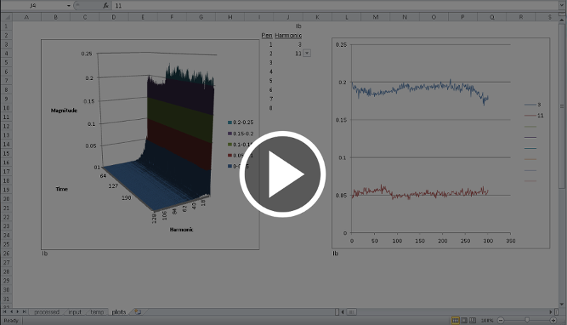
As I've played around with LTSPICE, I too have created various screencast videos that show certain features.  In the interest of sharing what I've learned I've included them here.  Enjoy.


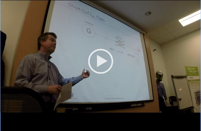
  • Video 1 (introduction, how to move around, how to run transient [waveform] and steady-state [AC analysis] simulation:
    https://pps2.com/v/s/1/lts.php

  • Video 2 (how to modify the schematic [delete, moving, inserting, changing values, etc.]):
    https://pps2.com/v/s/1/ltsb.php

  • Video 3 (LTSPICE symbols, modifying schematic to reduce simulation time)
    https://pps2.com/v/s/1/ltss.php
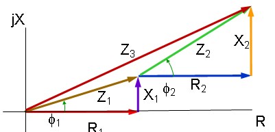
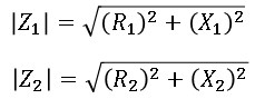
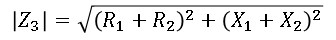
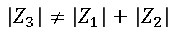
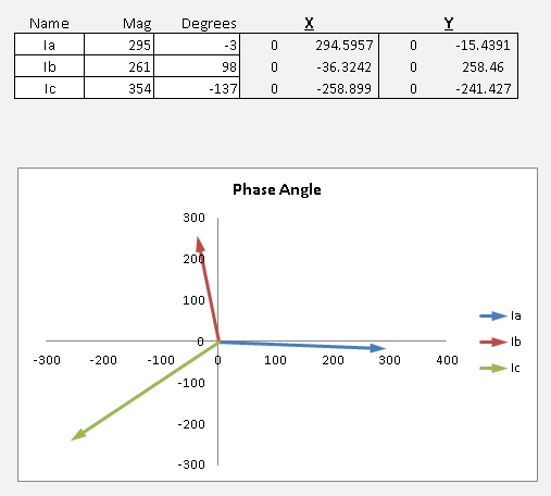
    In this video I made reference to a spreadsheet that converts between X/R and PF, computes R, X and L values based on desired system voltage and current and much more.  That spreadsheet (X over R2.xls) is attached below.

#32
3-Phase Power / Re: Power Systems Rules of Thumb
May 20, 2016, 09:22:57 PM
An even later, more up-to-date version of the same presentation.  I've included a video of me giving this particular version of the presentation to a class.

(Note: the system recording my lapel microphone switched off at about the 1 hour mark, so the remaining audio comes from the recording captured from a separate room mic)
(Note 2: There was a typo on slide 11 where it was supposed to say 86957 kVA, but instead said 86957 MVA!.  Corrected in this latest version)
#33
3-Phase Power / Re: Power Systems Rules of Thumb
May 12, 2016, 04:57:10 PM
Here's an updated version of this presentation.
#34
3-Phase Power / Low Voltage Utility Networks
May 10, 2016, 11:48:30 AM
The AC secondary network system have been used for many years (since 1920s!) to distribute electric power in the high-density, downtown areas of cities, usually in the form of utility grids. Modifications of this type of system make it applicable to serve loads within buildings.  The major advantage of the secondary network system is continuity of service. No single fault anywhere on the primary system will interrupt service to any of the system's loads. Most faults will be cleared without interrupting service to any load.  In fact, unlike "conventional" circuit breaker protected circuits, the network is designed so that a fault will 'burn clear' without interrupting current. 

The primary protective device used in a network is called the network protector (NWP).  Because the NWP is not designed to open during a fault downstream, protective relaying is different than on conventional systems connected to loop or main-tie-main systems.

I created a 30 minute narrated PowerPoint video that explains some of how a LV secondary network functions.

You can learn more by visiting the LV secondary network site at Eaton.com or by reading the power distribution engineering section within the Consulting Application Guide (CAG).  Secondary networks begins on page 14 (as of the date of this entry).
#35
3-Phase Power / Harmonic Trend Viewer
April 05, 2016, 01:00:51 PM
Starting with firmware version 13.3.5.7 on the PXM 4/6/8K Meters a new feature was added that offers the option to generate a harmonic capture .csv file (magnitudes only H1-H128) with matching waveform at every Load Profile interval. The capture is based on a 60 cycle waveform taken at the beginning of the Load Profile interval.

Since the data is stored in a comma separated variable file format, it is easy to open in Excel and view.  However since each row is a different time of a different harmonic, displaying this output file to show, for instance, the 3rd harmonic plotted over time would require sorting the data by harmonic number and then by time.

To simplify this work, we've created a spreadsheet that does this sorting for you.  As a bonus, a 3D and 2D time series graphs are included.

Check out my quick tutorial on how to use this program (or click on the video image below).
#36
3-Phase Power / Z vs R + jX fault calculations
February 02, 2016, 04:51:22 PM
A very acceptable first-pass approximation of determining fault current is to use impedance (Z), or more typically per unit (%Z).

However, when two or more impedances are connected in series, the sum of the absolute values of the separate impedances isn't exactly the same as the sum of the real and reactive parts of the impedance.  This can be shown graphically.


Here it is visually evident that the sum of the two impedances does not equal the actual series impedance, or mathematically:

but since:

and:

then:


Click on the image of the spreadsheet below to play back a voiced-over narration describing this issue, plus I explain how to use a spreadsheet tool to visualize the results.

Narrated explanation: https://pps2.com/v/1/ZvRX.php


Another thing that might be useful from this video is I show how to calculate and draw these stacked vector plots within Excel.  For more detail on creating phasor plots, refer to this separate article (Excel Phasor Diagram Builder)

Download the spreadsheet from the link below.
#37
3-Phase Power / Spoof Video - Basic Electricity
January 09, 2016, 04:33:48 PM
Dan Carnovale and I recorded a remake of a famous Cutler-Hammer spoof video entitled "Basic Electricity".  The same production company was used to make the "real" videos for the Eaton Power Systems Experience Center in Warrendale Pennsylvania, so while the video was a spoof, the production values were quite good.

Enjoy.

#38
3-Phase Power / Differential Ground Fault Protection
December 04, 2015, 08:46:29 AM


Differential ground sensing is useful in several situations:
  • Multiple, grounded sources on 3-phase, 4-wire system switched with 3-pole devices (neutral is not switched)
  • Current flow can reverse (this makes using ZSI more difficult to apply)

The following narrated screencast discusses how a differential ground system can be applied to isolate ground faults to within electrical switching systems (switchboards, switchgear) or even buildings.  This design does not require current transformer (CT) wiring to extend outside the zone of protection.

Narrated Screencast Differential GF Sensing: http://pps2.com/v/1/dgfs.php

The simulations shown in this model are based on LTSPICE.  More information on LTSPICE is available from http://www.linear.com/designtools/software/.  I've created another screencast that provides some basic information on how to use LTSPICE to run the simulations shown for this differential ground fault simulation.

Narrated Screencast LTSPICE: http://pps2.com/v/1/lts.php

Download LTSPICE simulation files: https://app.box.com/s/wib5s1biu901mhlungqc1fs611zt5iay/url]

Special Note:
Occasionally a different kind of differential protection will be necessary.  Refer to the following Eaton application notes for more information:
  • [url=http://www.eaton.com/ecm/groups/public/@pub/@electrical/documents/content/wp027003en.pdf]Ground fault isolation with loads fed fromseparately derived grounded sources[/url]
  • [url="http://www.eaton.com/ecm/groups/public/@pub/@electrical/documents/content/wp027004en.pdf"]Grounding methods in missioncritical facilities[/url]
#39
Harmonic summation and cancellation can be a tricky subject.  For example, why do 3rd harmonics sum in the neutral but cancel phase-to-phase?

To answer those questions, I created an Excel spreadsheet (attached at bottom of this article) that allows you to dial in various harmonics and see just what happens in the neutral as well as when measuring phase-to-phase voltage on two harmonic laden phases.


HINT: Summation and cancellation of 3rd harmonics are easier to understand when we remember that they are zero sequence.  That means that each phase harmonic is in-phase with each other.

Have fun!

Here's a quick screencast tutorial: https://pps2.com/v/1/hmc.php
#40
INCOM / IMPACC / Digitrip 520MC Communications
October 02, 2015, 02:11:27 PM
I've attached the most up-to-date version of the INCOM communication protocol description I have for this product. 

In particular, this includes the Extended Status Code (3 0 1) reply (code 47) to retrieve whether the breaker is in ARMS mode (Arcflash Reduction Maintenance System) or not.


#41
Figure 1: Example of drawing printed as scalable vector image


Advantage is that even scaled, no evidence of loss of resolution in image

When publishing a document, you know that what looks good on your screen doesn't necessarily look good printed, or worse, blown up to a wall size document.  For highest quality, scalable vector graphics look better than raster (scanned) images.  Scalable vector graphics are defined by mathematical equations, so they don't lose resolution when zoomed.

The easiest way I found of creating a vector graphic from inside programs like Excel or PowerPoint is to save the file as a PDF. 

However, some (many?) programs can't import a graphic image in PDF format.  Plus, even if you could, how do you extract just the graphic from a page that might also have a lot of text?

For that I use Inkscape.

The procedure I found that works best is the following:

  • From Inkscape, open the PDF file that you previously saved or printed from Excel, PPT, etc.
  • In Inkscape, from the File->Open menu, check the checkbox "import via Poppler"
  • Once imported, right-click on image and select "Ungroup"
  • Click away to deselect, then rubber band around any items you don't want (text, other images, etc.) and delete those items.
  • Save your cleaned up image as .eps (encapsulated postscript)

I've found that .eps works the best when importing graphics into Lyx (LaTeX front end editor).

Good luck!
#42
3-Phase Power / Excel Phasor Diagram Builder
September 25, 2015, 10:59:13 AM

I found that I needed to draw  phasor diagrams for some IEEE papers I was writing that would render properly when typeset.  I've included another article on how to export a scalable vector diagram, but here I just wanted to talk about the program I wrote that creates the diagram in the first place. 

Previously I had simply used a drawing program (like PowerPoint or Inkscape), but I wanted a diagram that was accurate to the degree.

So, I created this Excel program.  To use:

  • Cell B4: Enter in desired power factor
  • Cells B7-B17: Enter in any harmonic percentages
  • Cell B19: Enter power flow direction (+/-)
  • Cells Y2-Y3: Enter any scaling factors
    If these are left at the defaults of "1" for both voltage and current, each vector will be the same length (1).
  • Click to select either diagram, and select File->Print.  Only the selected diagram will print.
    If you are wanting to publish these diagrams, print to a PDF format and then refer to this other article on how to extract the diagram in a scalable vector format suitable for typesetting.
Here's a video that explains how to use this 1-phase phasor diagram builder: http://pps2.com/v/s/1/opd.php

I've also added a 3-phase phasor diagram builder.  Just plug in the 3 phasor's names (Ia, Va, Vab, etc.), the magnitude and phase angle (in degrees) and you will plot the 3 phasors.

Here's a video that explains how to use the 3-phase phasor diagram builder: http://pps2.com/v/s/1/tpd.php

Thirdly, if you are interested in creating stacked vector diagrams (vector connected to end of other vector), I wrote another article where I show how to do that (article actually on comparing differences between summed absolute values of impedance versus summing real (R) and reactive (X) components and I show graphically the differences using stacked vector diagrams).   Click to jump to that other article (or click on spreadsheet image immediately below): http://pps2.com/smf/index.php?topic=46.msg53#msg53
#43
Profibus / Profibus MINT (PMINT)
August 19, 2015, 04:01:05 PM

The Profibus DP MINT (PMINT) is a 1-to-1 converter device.  You will need one PMINT for every legacy INCOM device (e.g. circuit breaker trip units) that you wish to connect to a Profibus network.

For more information you can download the 66A7686 Instruction Leaflet (IL) from the Moeller (a division of Eaton) web site.

http://www.moeller.pl/Documentation/AWB/AWB1230-1621.pdf

For your convenience, a copy of this IL is attached below.
#44
VERY IMPORTANT
A request to read the Modbus MINT PRODUCT ID must always start at the PRODUCT ID 406255 register (underlying address 625410 or 186E16).  You can still read a block of registers (i.e. read other registers in the same message along with the PRODUCT ID register), but you must always start reading at the 406255 register.

Correct Example:
Modbus Address: 1
Starting Register: 406255 (register number) or 625410 (address)
Number of Registers to Read: 4 (collects both PRODUCT ID and Frequency (Hz))

The mMINT will return four 16-bit registers, the first two being the PRODUCT ID of the INCOM device associated with Modbus address 001 (which could be either a device with INCOM address 001 or could be something else if the mMINT routing tables are used to remap Modbus-to-INCOM addresses) and the second two the frequency as a 32-bit integer scaled by 10 (divide 32-bit number by 10 to get actual frequency).

Incorrect Example:
Modbus Address: 1
Starting Register: 406253 (register number) or 625210 (address)
Number of Registers to Read: 6 (collects Power Factor, PRODUCT ID and Frequency)

The mMINT will return six 16-bit registers, with the first two being the power factor, the next two being the PRODUCT ID and the last two being the frequency.  Because you didn't request PRODUCT ID as the first register in the table, the value returned will be INCORRECT.

Decoding Fast Status
The data returned in PRODUCT ID is the data returned using the INCOM "Fast Status" message.   You can read about the INCOM Fast Status message in the IMPACC protocol guide: http://www.eaton.com/ecm/groups/public/@pub/@electrical/documents/content/1030709222496.pdf#page=33

You'll notice that there are three 8-bit bytes returned, which contain a total of 24-bits.  Because Modbus registers are 16 bits long, you need two registers or 32 bits.  There won't be anything in the upper half of the second register (BYTE3 as described in INCOM protocol manual and how I display it in my Excel program). 

Notice that inside those 24 bits you see letters S, P, V and D with numbers after them.


"S" are status bits.  These describe the state of the device (open, closed, trip, alarm, etc.).   You see that bit S7 and S6 define whether the device is open, closed, tripped or alarm (for example, in a trip unit like the Digtrip 1150, alarm corresponds to a long delay pickup... you are going to trip if the current stays at this level).  S7 and S6 are the most significant bits of Byte 2 of the reply returned.  Note: the meaning of these bits can change depending on the type of device providing the Fast Status ... e.g. a trip unit versus a meter versus a transfer switch controller.

For example, if you look at the INCOM guide for the DT1150: http://www.eaton.com/ecm/groups/public/@pub/@electrical/documents/content/il17384c.pdf#page=136


So you see that S0-S5 provides additional information.  But you also see that the meaning of S4 differs depending on whether you have COMM VERSION 0 (bits V3-V0 are all zero) or if you have COMM VERSION 1 (bits V3-V1 are zero and V0 is one).

Here's another example...  an ATC-600. 

Checking out the ATC-600 (also known as the IQ Transfer II) you see from: http://www.eaton.com/ecm/groups/public/@pub/@electrical/documents/content/il17384f.pdf#page=61 that the Fast Status (and therefore what is returned in the PRODUCT ID register in the Modbus MINT is as follows:


Using the mMINT Excel program, and reading the PRODUCT ID register, you might get something that looks like this:


We see that the values returned are:
BYTE0 / B0 = 196  (C416)
BYTE 1/ B1 = 84  (5416)
BYTE 2 / B2 = 195 (c316)

Converting these hexadecimal values into binary (to see the individual bits) we have the following:


Now you can segregate the bits into their groups.  Starting with the Division Code, we see the following:
BYTE0:

   Converting this Division code from binary to decimal we have 4 ... the correct value 

Now looking at the Communication Version we take the top 2 bits of BYTE0 and the bottom (least significant) 2 bits from BYTE1:

   Converting this Communications Version from binary to decimal we have 3.  From the list above:


Now looking at the remaining bits in BYTE1
BYTE1:

   Converting this PRODUCT ID from binary to decimal we have 16+4+1 = 21 ... the correct value 

Now finishing with BYTE2:

Both bits S6 and S7 are on, so we are in alarm: 

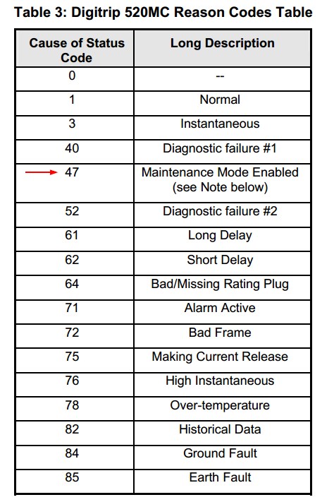
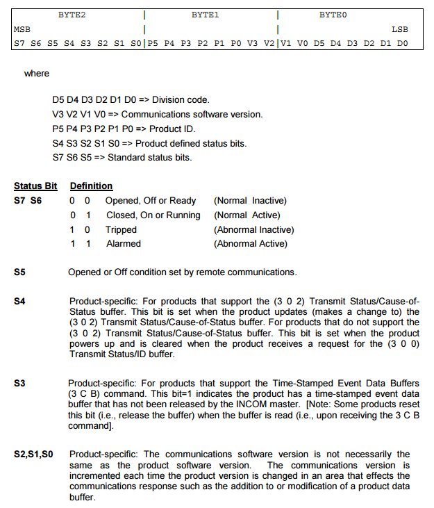
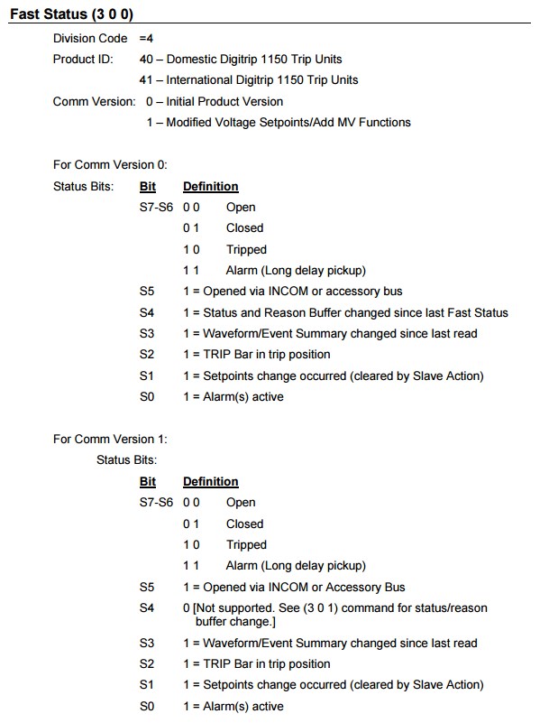
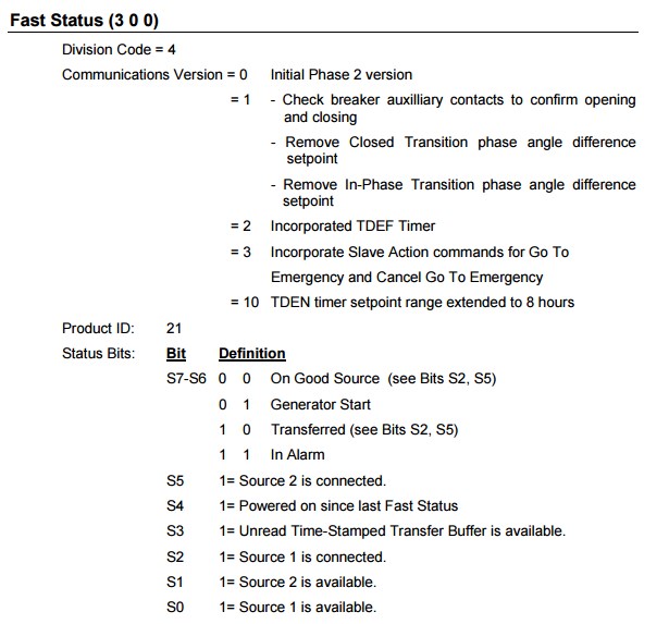
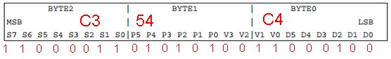
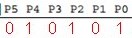
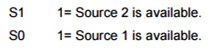
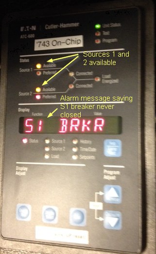
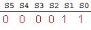
   Only bits S0 and S1 are on, so both sources are available.


Sure enough, when we look at the faceplate of the ATC, that is what we see... both sources are available and we are in alarm!
#45
3-Phase Power / Power Systems UPS
June 10, 2015, 03:45:55 PM
The presentation below covers some of the important topics that are top of mind for data center owners and operators today.


  • UPS multi-mode / ECO-mode (ESS)
  • Financial analysis
  • VMMS
  • Power Supply Unit (PSU) Tested Performance
  • Coordination and Timing of switching (Eco-mode vs STS vs PSU hold-up timing

The audio for the presentation (YG_Loucks_Day2_UPS.pptx) attached below can be downloaded from here.

I recently updated the presentation to include new material (2- and 3-level converters, etc.) and created a voiced-over presentation that you can play by clicking on the image below.  The updated presentation that goes with this is also attached below (YG_Loucks_Day2_UPS_c.pdf).