News:

Calling all communications systems experts - please share your knowledge here!

Main Menu
Menu

Show posts

This section allows you to view all posts made by this member. Note that you can only see posts made in areas you currently have access to.

Show posts Menu

Topics - Dave Loucks

#1
INCOM / IMPACC / DT1150 Configuration Tool
July 21, 2022, 11:53:53 PM
As users of the Westinghouse/Cutler-Hammer/Eaton Digitrip 1150 (DT1150) know, there is no tool available to edit or backup/restore a DT1150 trip unit.

While developing the code to configure this product using the Eaton Device Configuration Management Software (DCMS, or internally to Eaton known as "No Touch / Low Touch Loader or NTLT), we needed a configuration file to save in the cloud for this product.

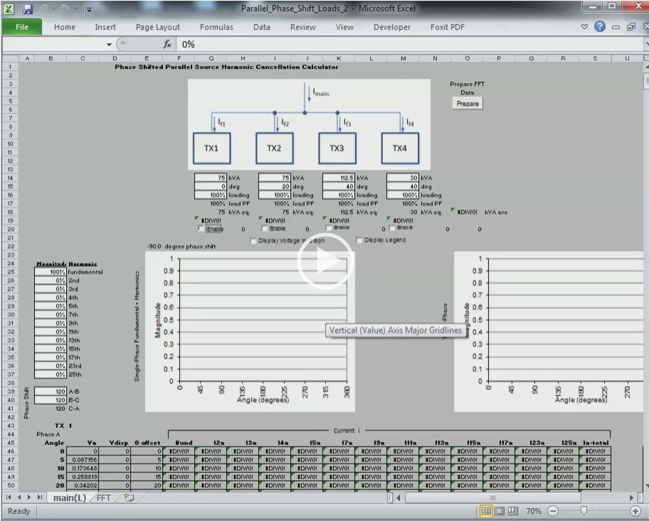
Since none existed, we developed our own based on a simple multi-column CSV (comma separated values) format.  Since the file was a bit cryptic to interpret, we also created some macros within Excel VBA that would convert the file into something more readable.

Click on the link below to download the file and an example DT1150 configuration file.

https://pps2.com/smf/index.php?action=dlattach;topic=238.0;attach=136
#2
Motor Control / C440
May 09, 2019, 04:00:10 PM
Went looking for instructions for the Modbus RTU add-in module for the C440 overload relay and had trouble finding it.  So am putting a copy below.
#3
The DT1150 electronic trip unit supports both reading and writing (changing) the status of the ARMS mode.  The ARMS status is held in message 59 of the INCOM 3 C 9 "Read Setpoints Buffer".

From page 49 of the latest IL17384 (Part C - Protective Relays and Trip Units INCOM/IMPACC protocol guide)


Note: "not changeable" means the mode was set by the switch and software cannot change the state unless the switch is  off.

Access the DT1150 Setpoints Buffer - Maintenance Mode status using Modbus messages:
Setpoints Buffer Description command 3 C 9 is an Incom command that can be used to poll Maintenance mode status.
Message 59 of the response data indicates Maintenance Mode Status.

Using the Modbus MINT this setting change read or changed by sending different Modbus RTU message.

The screenshots shown below are based on the ComTestPro Modbus utility available for free from http://www.baseblock.com/PRODUCTS/comtestpro.htm

On the Modbus master side:
Using func code 16
Write C3BEh to 6000h
Write 9002h to 6001hM
Note the 2 in 9002 is the Incom address


Then with function code 3 read 122 registers from 6000h


The 212th byte after the Modbus message byte count [F4h] is byte 0 of Message 59 which is Maintenance mode status.

Byte 212 highlighted below indicates changing from 02h to 03h, confirming toggle of Maintenance Mode.

Maintenance Mode is OFF

WRITE to 6000h/6001h
Baseblock ComTest Pro for Modbus Devices, Version: 2.0.5.1
Clear Log : Start > 11/23/2015 11:07:43 AM           
11:07:56.517: Com1, Baud Rate: 9600, Data Bits: 8 Bits, Parity: None, Stop Bits: 1 Stop Bit
11:07:56.517: Echoback: Off, RTS Control: Off, Transmit Delay: 5 ms, Response Delay: 3000 ms
11:07:56.520: Write Holding Register(s)
11:07:56.520: Device Address: 02h, Register: 6000h, Number of Registers: 2
11:07:56.521: |-> Write Register: 6000h, Number of Registers : 2
11:07:56.528: -> [02h] [10h] [60h] [00h] [00h] [02h] [04h] [C3h] [BEh] [90h] [02h] [E5h] [48h]
11:07:56.567: <- [02h] [10h] [60h] [00h] [00h] [02h] [5Fh] [FBh]


READ from 6100h
11:08:59.881: Com1, Baud Rate: 9600, Data Bits: 8 Bits, Parity: None, Stop Bits: 1 Stop Bit
11:08:59.882: Echoback: Off, RTS Control: Off, Transmit Delay: 5 ms, Response Delay: 3000 ms
11:08:59.885: Read Holding Register(s)
11:08:59.885: Device Address: 02h, Register: 6100h, Number of Registers: 122
11:08:59.885: |-> Read Register: 6100h, Number of Registers : 122
11:08:59.895: -> [02h] [03h] [61h] [00h] [00h] [7Ah] [DBh] [E6h]
11:09:00.289: <- [02h] [03h] [F4h] [3Dh] [00h] [89h] [0Ah] [00h] [00h] [00h] [00h] [FDh] [00h] [FFh] [E7h] [A0h] [00h] [00h] [00h] [00h] [00h] [01h] [04h] [D0h] [00h] [28h] [07h] [28h] [00h] [05h] [64h] [FEh] [00h] [03h] [02h] [14h] [00h] [F0h] [14h] [0Ah] [00h] [05h] [32h] [FFh] [00h] [00h] [00h] [00h] [00h] [00h] [00h] [00h] [00h] [00h] [00h] [00h] [00h] [78h] [14h] [05h] [00h] [03h] [FFh] [0Ah] [00h] [32h] [0Ah] [05h] [00h] [00h] [FEh] [14h] [00h] [78h] [0Ah] [05h] [00h] [01h] [FFh] [19h] [00h] [64h] [0Ah] [01h] [00h] [03h] [FEh] [0Ah] [00h] [32h] [0Ah] [01h] [00h] [00h] [FEh] [00h] [00h] [00h] [00h] [64h] [00h] [00h] [02h] [00h] [00h] [00h] [00h] [19h] [00h] [00h] [00h] [00h] [00h] [00h] [00h] [55h] [00h] [01h] [FEh] [00h] [00h] [00h] [00h] [00h] [00h] [00h] [00h] [00h] [00h] [00h] [00h] [00h] [00h] [00h] [00h] [00h] [00h] [00h] [00h] [00h] [00h] [00h] [00h] [00h] [00h] [00h] [00h] [00h] [00h] [00h] [00h] [00h] [00h] [00h] [00h] [00h] [00h] [00h] [00h] [00h] [00h] [00h] [00h] [00h] [00h] [00h] [00h] [00h] [00h] [00h] [00h] [00h] [00h] [00h] [00h] [00h] [00h] [00h] [00h] [00h] [00h] [00h] [00h] [00h] [00h] [00h] [00h] [00h] [00h] [00h] [00h] [00h] [00h] [00h] [00h] [00h] [00h] [00h] [00h] [00h] [00h] [00h] [00h] [00h] [00h] [00h] [00h] [00h] [00h] [00h] [00h] [00h] [00h] [00h] [00h] [00h] [00h] [00h] [00h] [00h] [00h] [00h] [00h] [00h] [00h] [00h] [00h] [0Eh] [00h] [00h] [00h] [00h] [00h] [00h] [00h] [02h] [00h] [00h] [00h] [00h] [00h] [00h] [00h] [00h] [00h] [00h] [00h] [79h] [02h]


Note the 02h value in the 59th message.  From Maintenance Mode Action field above, 02h is confirmed to be OFF (not changeable).  However, what the really means is that the ARMS was switched off by the switch on the trip unit.  Since the switch is off, you can override that value in software.

Maintenance Mode is turned ON

WRITE to 6000h/6001h
11:10:19.387: Com1, Baud Rate: 9600, Data Bits: 8 Bits, Parity: None, Stop Bits: 1 Stop Bit
11:10:19.387: Echoback: Off, RTS Control: Off, Transmit Delay: 5 ms, Response Delay: 3000 ms
11:10:19.395: Write Holding Register(s)
11:10:19.400: Device Address: 02h, Register: 6000h, Number of Registers: 2
11:10:19.403: |-> Write Register: 6000h, Number of Registers : 2
11:10:19.412: -> [02h] [10h] [60h] [00h] [00h] [02h] [04h] [C3h] [BEh] [90h] [02h] [E5h] [48h]
11:10:19.451: <- [02h] [10h] [60h] [00h] [00h] [02h] [5Fh] [FBh]


READ from 6100h
11:10:29.813: Com1, Baud Rate: 9600, Data Bits: 8 Bits, Parity: None, Stop Bits: 1 Stop Bit
11:10:29.817: Echoback: Off, RTS Control: Off, Transmit Delay: 5 ms, Response Delay: 3000 ms
11:10:29.823: Read Holding Register(s)
11:10:29.827: Device Address: 02h, Register: 6100h, Number of Registers: 122
11:10:29.831: |-> Read Register: 6100h, Number of Registers : 122
11:10:29.840: -> [02h] [03h] [61h] [00h] [00h] [7Ah] [DBh] [E6h]
11:10:30.232: <- [02h] [03h] [F4h] [3Dh] [00h] [89h] [0Ah] [00h] [00h] [00h] [00h] [FDh] [00h] [FFh] [E7h] [A0h] [00h] [00h] [00h] [00h] [00h] [01h] [04h] [D0h] [00h] [28h] [07h] [28h] [00h] [05h] [64h] [FEh] [00h] [03h] [02h] [14h] [00h] [F0h] [14h] [0Ah] [00h] [05h] [32h] [FFh] [00h] [00h] [00h] [00h] [00h] [00h] [00h] [00h] [00h] [00h] [00h] [00h] [00h] [78h] [14h] [05h] [00h] [03h] [FFh] [0Ah] [00h] [32h] [0Ah] [05h] [00h] [00h] [FEh] [14h] [00h] [78h] [0Ah] [05h] [00h] [01h] [FFh] [19h] [00h] [64h] [0Ah] [01h] [00h] [03h] [FEh] [0Ah] [00h] [32h] [0Ah] [01h] [00h] [00h] [FEh] [00h] [00h] [00h] [00h] [64h] [00h] [00h] [02h] [00h] [00h] [00h] [00h] [19h] [00h] [00h] [00h] [00h] [00h] [00h] [00h] [55h] [00h] [01h] [FEh] [00h] [00h] [00h] [00h] [00h] [00h] [00h] [00h] [00h] [00h] [00h] [00h] [00h] [00h] [00h] [00h] [00h] [00h] [00h] [00h] [00h] [00h] [00h] [00h] [00h] [00h] [00h] [00h] [00h] [00h] [00h] [00h] [00h] [00h] [00h] [00h] [00h] [00h] [00h] [00h] [00h] [00h] [00h] [00h] [00h] [00h] [00h] [00h] [00h] [00h] [00h] [00h] [00h] [00h] [00h] [00h] [00h] [00h] [00h] [00h] [00h] [00h] [00h] [00h] [00h] [00h] [00h] [00h] [00h] [00h] [00h] [00h] [00h] [00h] [00h] [00h] [00h] [00h] [00h] [00h] [00h] [00h] [00h] [00h] [00h] [00h] [00h] [00h] [00h] [00h] [00h] [00h] [00h] [00h] [00h] [00h] [00h] [00h] [00h] [00h] [00h] [00h] [00h] [00h] [00h] [00h] [00h] [00h] [0Eh] [00h] [00h] [00h] [00h] [00h] [00h] [00h] [03h] [00h] [00h] [00h] [00h] [00h] [00h] [00h] [00h] [00h] [00h] [00h] [84h] [C1h]


Since the payload in INCOM messages is 24-bits long, and since Modbus RTU messages have 16-bit registers, the Modbus MINT uses two 16 bit registers (4-bytes) for one INCOM message. 


The DT1150 setpoint Buffer is 61 messages (61*4 = 244 [0xF4] bytes long).   Note the 03h value in the 59th message indicating that ARMS mode is activated via a switch or contact closer (it would be 01h if it were activated via the communications channel)

Changing this value is much more involved compared to simply reading it since the Modbus MINT requires that each separate INCOM message be sent as a separate Modbus message (and the Setpoint command has 61 separate messages plus a checksum message for 62 total!)  See INCOM Pass-Through Messaging via Modbus MINT for more details on how this is done.
#4
Modbus / Low cost 485 adapter for your computer
February 12, 2018, 05:05:57 PM
Modern computers are no longer supplied with serial ports (other than Ethernet and USB), and even back when they did they were supplied, they were RS-232.  Even then to get an RS-485 connection, you'll need a converter.

There are ton of high quality converters from companies like B&B Electronics, but if all you want is an inexpensive 2-wire USB to RS-485 converter, this one has been tested and works fine with the VBA_COMMS program.

Don't expect it to withstand the rigors of an industrial environment, but if you are looking for a low cost way of programming the Modbus MINT, this is a great choice (at least in February 2018 when this article was written).


Here's a wiring diagram showing how the JBTech USB to RS485 adapter would be wired to the Modbus MINT (mMINT).  Note that I used electrical tape to secure the cable to the USB adapter.  The screw terminal landing on the USB adapter is not very robust.


#5
3-Phase Power / Induction Motor Theory
January 15, 2018, 02:00:12 PM
Not sure how helpful this will be, but I presented a talk on how an induction motor operates.  Covers some basic rules about Faraday's Law, Lorenz Forces and just in general how you convert electrical current into motion. 

HTH
#6
Video Tutorials / Directory
June 06, 2017, 09:54:02 AM
These videos are mostly throughout this website.  I've just copied them here to a single page for convenience.


LTSPICE simulation export, resampling and decimation tutorial  https://pps2.com/v/s/1/ltsd.php
Low Voltage Underground Utility Networks  https://pps2.com/v/s/1/nwp.php
Ethernet Networks  https://pps2.com/v/s/1/etht.php
Using Excel to Display Waveforms and Phasor Diagrams  https://pps2.com/v/s/1/opd.php
Using Excel to Display Three-Phase Phasor Diagrams From X-Y Data  https://pps2.com/v/s/1/tpd.php
SFTP Connection to PXMP Meter  https://pps2.com/v/s/1/occn1.php
Using Excel to Generate and Display 3-Phase Harmonics  https://pps2.com/v/s/1/3h.php
Adding the Analysis Tool-Pack to Excel  https://pps2.com/v/s/1/atp.php
Calculating, Displaying and Normalizing FFT Collected From Multiple Devices  https://pps2.com/v/s/1/ceifft.php
Measuring Harmonic Attenuation Using Programmable Phase-Shifted Transformers  https://pps2.com/v/s/1/hmtc.php
Performing Arbitrary Math Functions Within COMTRADE Excel Importer Program  https://pps2.com/v/s/1/cei_math.php
Comparison of Performance Using Zone Selective Interlocking (ZSI) Versus Arcflash Reduction Maintenance System (ARMS)  https://pps2.com/v/s/1/zsi_arms.php
Understanding Differential Relay and CT Matching  https://pps2.com/v/s/1/diff_relay.php
Using the COMTRADE Excel Importer to Determine RMS Values  https://pps2.com/v/s/1/cei_rms.php
Understanding Security When Connecting to a Java Enabled Power Xpert Meter  https://pps2.com/v/s/1/pxmv.php
Harmonic Summation and Cancellation (Phase and Ground)  https://pps2.com/v/1/hmc.php
LTSPICE Quickstart Tutorials Part 1:   https://pps2.com/v/s/1/lts.php
LTSPICE Quickstart Tutorials Part 2:   https://pps2.com/v/s/1/ltsb.php
LTSPICE Quickstart Tutorials Part 3:   https://pps2.com/v/s/1/ltss.php
Power Systems Rule of Thumb (Recording of Instructor Led Class)  https://pps2.com/v/s/1/yg_1.php
(New Version) Power Systems Rule of Thumb (Recording of Instructor Led Class)  https://pps2.com/v/s/1/yg_1a.php
Using Excel to Create Harmonic Trend Viewer for PXM4/6/8K Meters  https://pps2.com/v/1/htv.php
Comparing Fault Current Calculations using "Z Method" Versus the "R+jX Method"  https://pps2.com/v/1/ZvRX.php
Designing Higher Efficiency Mission Critical Power Systems  https://pps2.com/v/s/1/yg_4.php
(New Version) Designing Higher Efficiency Mission Critical Power Systems  https://pps2.com/v/s/1/yg_4a.php
Power System Load Flow and Power Factor Correction Calculations (Recording of Instructor Led Class)  https://pps2.com/v/s/1/yg_3.php
(New Version) Power System Load Flow and Power Factor Correction Calculations (Recording of Instructor Led Class)  https://pps2.com/v/s/1/yg_3a.php
Power System Protection and Coordination (Recording of Instructor Led Class)  https://pps2.com/v/s/1/yg_2.php
(New Version) Power System Protection and Coordination (Recording of Instructor Led Class)  https://pps2.com/v/s/1/yg_2a.php
Predicting, Measuring and Abating Transients on Medium Voltage Systems with Vacuum Switching  https://pps2.com/v/1/cp.php
Modbus MINT Programmer Tutorial  https://pps2.com/v/1/mmint08.php
Modbus MINT Programmer Cloud Backup and Restore  https://pps2.com/v/1/br.php
Modbus MINT Programmer Issuing Control Commands to INCOM Device  https://pps2.com/v/1/control.php
Creating PXG900 Offline Configuration File  https://pps2.com/v/s/1/sstd0.php
Differential Ground Fault Sensing  https://pps2.com/v/1/dgfs.php
#7
Legacy Motor Control / Westinghouse Advantage MCC
April 20, 2017, 02:21:49 PM
The Advantage MCC was introduced in 1991 and was Westinghouse's first networked motor control. 

I wrote a paper on this way back in 1993 entitled "Low-voltage motor control centers utilizing microprocessor technology".  See http://ieeexplore.ieee.org/document/231982/

Download the Instruction Booklet IB 8922-1 attached below.
#8
Legacy Motor Control / Westinghouse Type W MCC
April 20, 2017, 01:55:24 PM
Legacy Westinghouse MCC that was available from roughly 1965 to 1979

Download the instruction book IB12-129 dated July 1978 below.

You can learn more about vintage Westinghouse products (and parts for those products) at http://www.eaton.com/ecm/groups/public/@pub/@electrical/documents/content/ca08100014e.pdf
#9
As I get around to it, I'll scan and add more cards.  If you need an instruction booklet for an I/O module that isn't listed here, let me know (dgloucks at gmail dot com)

  • NL-740
    2-channel, 12-bit isolated, differential input analog input module
  • NL-742
    8-channel, 10 bit singled ended input analog input module
  • NL-743
    16-bit TTL register input module
  • NL-744
    8 or 16 multiplexed 16-bit TTL register input module
  • NL-750
    2 channel, unipolar 12 bit analog output
  • NL-751
    4-channel, 11 bit (10 bits + 1 sign bit) analog (voltage) output
  • NL-752
    4-channel, 10 bits, analog (current) output
  • NL-753
    16-bit TTL register output module
  • NL-753
    8 or 16-channel multiplexed TTL register output module
#10
Article 240.87 in the NEC mentions that ZSI and something called "energy reducing maintenance switching with local status indicator" are two ways of meeting the requirements of this article. 

What is ZSI?  How is Eaton's version of the "energy reducing maintenance switching" (called ARMS) different from other vendor's versions?

Click on the image below to view a screencast of me presenting the contents in the attached PPT file below.

#11
Article 240.87 in the National Electrical Code describes using differential protection as one of the options to use if you have a breaker rated 1200 A or higher.  But just what is differential protection and why should or shouldn't be used?

This presentation gives an overview of how differential relaying operates and includes a discussion of CT accuracy and how high resistance loads (e.g. long CT conductors, small wire gauge CT conductors or high impedance loads) affect differential relaying accuracy.

Click on the image below to view a screencast of me presenting the contents in the attached PPT file below.

#12
3-Phase Power / Conductor Temperature Ratings
January 10, 2017, 02:52:05 PM
Conductors and bus generate heat when current flows through them.  How much heat?  That depends on the conductor size, the application and many other factors.

For electrical equipment, such as switchgear, switchboards, motor control centers and panel boards, the manufacturer has received certification from UL that at rated current the bus, terminals, connection points and lugs are below the maximum temperature rating permitted by UL.

But what if you want to operate the equipment at an even cooler temperature than this maximum allowable temperature?  How much would you need to reduce the current to reduce the temperature?

That's a tricky question because the temperature of equipment likely isn't proportional to the power dissipated.  Cooling plays a factor and that cooling too is non-linear with temperature.

Can we at least estimate changes in temperature based on changes in current flow?

One place to start as a first pass approximation is IEEE 399-1997 (Brown Book) where in section 13.4.1, equation 13-5, an "adjustment factor" is calculated for when you want to change either the conductor temperature rating or the ambient temperature:

Where:


Tc  Conductor rated temperature in oC at which the base ampacity is specified
Tc'  Maximum allowed conductor temperature in oC
Ta  Ambient temperature in oC at which the base ampacity is specified
Ta'  Other ambient temperature oC at which the conductor will be applied

I'm assuming copper conductors here.  You'd use equation 13-6 if you wanted aluminum conductors (just change 234.5 to 228.1 both times).

In our example:
Tc            = 105oC (40 + 65)
Tc'          = 70oC (40 + 30)
Ta           = 40
Ta'          = 40 (no change)


So, this would imply that if you ran the conductor at no higher than 72% of its rated capacity (or better, 71%) the conductor temperature would not rise more than 30oC above a 40oC ambient.

Consider this only back of the envelope calculations since it could be better (there is might be better air circulation) or worse (you might have harmonics which will induce eddy current heating)

Here's a calculator that automates this math:


You can click on the image above to download, or select "conductor_temp_rerating.xlsx" from below.
#13
Power Xpert Gateway / PXG Configuration
January 03, 2017, 03:02:28 PM
While you can certainly just plug in a browser and configure a PXG900, there are a couple of things you should know to make things go more smoothly.

If you are using a Windows PC and have admin rights, you might want to consider using the micromini-USB connection on the front of the PXG900 (formerly a type A USB connection on the "E" series gateways).  The default address for that port is always 192.168.200.101.  The disadvantage is you will need to load a USB driver onto your computer (instructions) and you will need Admin rights to allow that.

If instead you use the Ethernet port, you should know that this port supports Zero Config and that means that the default IP address can move around!  While the default IP address on the Ethernet port following a factory reset is https://169.254.1.1 (or http://169.254.1.1), that will only be the case if nothing else is "heard" when the PXG boots.  Best bet is to make sure nothing is connected to the network 1 port during a factory reset. 

Once you are able to connect with the gateway and have changed the IP address to a new fixed (static) value, zero config is disabled and you'll have a good known fixed IP address for the PXG.

But why mess around with all this?  Did you know there was an "low touch" loading method for the PXG900? (actually also works on the "E" series, i.e. PXG200E, 400E, 600E, and 800E gateways with latest firmware too).  You'll still need admin rights to both load this program and load the USB driver (which the installer does automatically).

The "Configuration Automator" program (link at end of this topic) removes a lot of the complexity when you are tasked with loading the PXG configuration.  It does this by semi-automatically installing an XML file that contains the settings you wish to install.

This XML file can be created a number of ways, but perhaps the easiest is to use the PXG offline configuration spreadsheet.


You can download a copy of the offline configurator and try it yourself (if this deep link has expired -- which it might when the program is updated -- just navigate to https://eaton.com/pxg and select "PXG900 Offline Config Tool" under the "Software Downloads" section in the "Documentation" tab.


Here are some screencast videos that explain how these programs work:
#14
Numa Logic Programmable Controllers / NL-300 Information
November 30, 2016, 08:20:16 AM
Numa-Logic NL-300 series control was a system of separate cards, with each card having a separate function (AND, OR, Flip-Flop, etc.)  These cards were mounted in a rack and the "logic" was performed by connecting various gates and circuits of each card together using wire-wrapping techniques.

Manuals and other documentation is available at: http://www.pps2.com/communications/NL300.php

#15
3-Phase Power / Using Phase Shifting to Cancel Harmonics
November 22, 2016, 09:40:51 PM
Putting some loads downstream of transformers that have different phase shifts is a well-known method of cancelling harmonics.  But how much cancellation?  And what amount of phase shift should I use -- 15 degrees, 20 degrees, 30 degrees, 45 degrees?

To answer that question I created a calculator that allows you to select from 1 to 4 parallel transformers, each with programmable kVA rating and phase shift, and measure the amount of harmonic attenuation you might see in such a configuration.

Take a look at the 9-minute tutorial video on how these programs work and download them from the links below.


Attached a later version (V3) to add 17th & 19th harmonics and clean up some errors that occur if you selected 3 or 4 parallel transformers.
#16
Power Xpert Meter / Power Xpert Multi-Point (PXMP) meter
November 10, 2016, 02:48:55 PM
Need to get any information from the Energy Portal Module in the PXMP?  You can FTP (actually SFTP, which is FTP running through an SSH tunnel) directly to the file structure in the meter and download the files.

Here's an example using FileZilla (this address is behind the Eaton firewall so unless you work for Eaton just consider this an example... you will substitute your device's actual IP address)

Host: sftp://10.130.15.28  (assume you are behind the Eaton firewall for this test)
Username: ftp
Password: ftp
Port: 2222


Here's a video showing step-by-step how you access those files: https://pps2.com/v/s/1/occn1.php


EAllocation Software
Eaton also offers a more automated method of collecting these files.  Just download the free EAllocation software.  You can also download the manual.

EAllocation will automatically extract (via behind the scenes SFTP) and calculate kWh by month, by meter, by user. You can then export, print or email this data.

Here's another video / screencast I made showing how to use this software to download and allocate energy: https://pps2.com/v/s/1/occn2.php


#17

Having trouble connecting to versions of the Power Xpert 4000, 6000 or 8000 (4/6/8K) meters using the Java applet served from the PXMs?  The HTML5 version of the PXM doesn't have these problems, but if you have problems connecting to the Java version of the meter, you may have a Java security setting issue. 

Take a look at the attached document for fixing that (and other) problems.
#18


Recently I was involved in the troubleshooting of multiple Modbus networks that were identical in devices, distances, programming, configuration, and termination resistance, but on some of the networks, there would be no communications. 

Interestingly, when a Modbus test program (VBA Comms) replaced the existing Modbus master on the non-functioning network (using the same line driver used by the SCADA master), all the devices talked! 


This pointed to something being wrong with the SCADA master. 

But before you jump to that conclusion, allow me to complicate things by performing another test.

In this test the existing SCADA master was reconnected, but "known good" Modbus slave devices from functioning networks replaced the Modbus slave devices on the non-functioning network.  The existing SCADA master was able to talk to them fine! 


So, in the first case, it appeared that something was wrong with the SCADA master, but in the second, it looks like something is wrong with the slaves.


  • VBA Comms as SCADA master
    All slave devices worked on all networks
  • Existing SCADA master
    Some slave devices worked with all SCADA masters
    Some slave devices would not work with any SCADA masters

What is going on?

The problem was believed to be (but not expressly confirmed as of this date) that the signal levels on the "bad" network was right at the ragged edge of being detectable at the slave devices.

Then why did the laptop running VBA Comms always work?

The belief is that the SCADA master, that master's line driver -- which turned out to be self-powered from current provided by that SCADA master -- and the slave device internal loading impedance all played a role.

The Rest of the Story
232 to 485 converters that don't require external power supplies are less expensive and easier to install than converters that require external power.  The "self-powered" units operate by extracting voltage from one of the 232 pins that is expected to be high (e.g. DTR pin) and use this signal to not only power the line-driver's electronic circuitry, but also to have enough left over to send a 485 signal (with sufficient amplitude) down the 485 network to all the connected devices and termination resistances.

Since 485 networks require signals greater than 300 mV and since most 232 ports provide more than 5-12 volts, normally there should be no problem.

The problem occurs when the 232 source voltage is current limited, or must provide current for other loads (which might vary, contributing to the maddeningly intermittent nature of this problem). 

If the line driver electronics draws too much load, or if the load impedance of the network is too low, or if the sourcing 232 device voltage (or available current) varies, the voltage on the 485 network can be too low to be detected reliably by the other 485 devices.  Recall that any voltages less than 300 mV (i.e. between -300 mV and +300 mV) are undefined in the 485 spec.

Undefined voltages will result in symptoms such as "framing errors" on received messages.

For short networks (<1000 feet, 300m end-to-end), one quick fix is to remove one or both termination resistors. 

Removing the termination resistances will reduce the load on the biasing circuit in the line driver (232/485 converter) and the signal levels will increase, potentially fixing the problem, as it did in this application.  Because of the intermittent nature and how long it took to resolve, the customer couldn't spend any more time performing "post-fix" voltage checks, so we are not sure how close to the 300 mV we were before and how much margin we had after.

If this happens to you and in the case you are using the Modbus MINT as a network slave device, you can detect this framing error problem by interrogating the "Table 6" registers within the mMINT using the VBA Comms tool.  The smoking gun is an increase in the number of UART framing errors reported.

  • Connect your computer running VBA Comms as the Modbus master on the "bad" network.
    Verify able to communicate to the mMINT.
  • Press the "Send Reset" button found on the mMINT tab in VBA Comms.
    This will reset all the error counters to zero (assuming you actually originally had good communications from VBA Comms to the mMINT in the first place!)

  • Disconnect VBA Comms and reconnect to the existing Modbus master that can't talk to mMINT.  Let it attempt to poll for a while (collect about 20-30 flashes on the Modbus Rx light on the mMINT).
  • Disconnect the Modbus master and reconnect VBA Comms
  • Press the Re-Read Diags button.

  • What values are the highest value?
    If "UART framing error" is a large value, and assuming you have selected the proper bit rate in this program to match that of the master and the slaves, then likely the networking biasing issue is to blame.  As mentioned above, if the network is short (<1000 ft, 300 m), remove one or both termination resistors as a possible work around

The proper fix is to use a line driver that can output sufficient signal.  If the 232 device you have connected the line driver to cannot provide sufficient current, then substitute the line driver with one that is separately powered.

#19
School is great.  Not just for the technical education, but for the interaction with professors, peers and others as you learn how to balance the need to complete your assignment, course, paper or project all the while dealing with the other "non-school" issues of life.

But nothing stays the same.  As available knowledge in a topic grows, what do you not teach the students?  Time is such a precious resource, that knowing how to allocate it wisely for learning is more important than ever.

Life is more than just a (technical) education.  Getting one's priorities right helps us navigate better.

After pondering this for a while, I thought I'd write down a list of the things I wished I'd paid more attention to in my early years.   

If you are interested, I've also copied below an mp3 audio file of me giving this presentation to a group of electrical and computer engineering students at the University of Pittsburgh on 6-SEP-16.
#20
3-Phase Power / LTSPICE
June 13, 2016, 11:01:44 AM
You may have noticed that in several of the postings on this site I mentioned that Linear Technology offers a free SPICE program that can be downloaded from their website.  The built in help talks about some tutorials, which while I haven't reviewed in detail, look great from a cursory scan:

There are also independent user groups and forums.  The one I use the most is:  https://groups.yahoo.com/neo/groups/LTspice/info.

As I've played around with LTSPICE, I too have created various screencast videos that show certain features.  In the interest of sharing what I've learned I've included them here.  Enjoy.


  • Video 1 (introduction, how to move around, how to run transient [waveform] and steady-state [AC analysis] simulation:
    https://pps2.com/v/s/1/lts.php

  • Video 2 (how to modify the schematic [delete, moving, inserting, changing values, etc.]):
    https://pps2.com/v/s/1/ltsb.php

  • Video 3 (LTSPICE symbols, modifying schematic to reduce simulation time)
    https://pps2.com/v/s/1/ltss.php
    In this video I made reference to a spreadsheet that converts between X/R and PF, computes R, X and L values based on desired system voltage and current and much more.  That spreadsheet (X over R2.xls) is attached below.