- Welcome to LEC Forum.

Recent posts
#41
Publication Techniques / Creating "Vector" rather than ...
Last post by Dave Loucks - September 25, 2015, 11:22:11 AMFigure 1: Example of drawing printed as scalable vector image
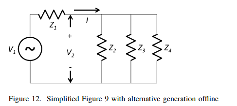
Advantage is that even scaled, no evidence of loss of resolution in image

When publishing a document, you know that what looks good on your screen doesn't necessarily look good printed, or worse, blown up to a wall size document. For highest quality, scalable vector graphics look better than raster (scanned) images. Scalable vector graphics are defined by mathematical equations, so they don't lose resolution when zoomed.
The easiest way I found of creating a vector graphic from inside programs like Excel or PowerPoint is to save the file as a PDF.
However, some (many?) programs can't import a graphic image in PDF format. Plus, even if you could, how do you extract just the graphic from a page that might also have a lot of text?
For that I use Inkscape.
The procedure I found that works best is the following:
I've found that .eps works the best when importing graphics into Lyx (LaTeX front end editor).
Good luck!
Advantage is that even scaled, no evidence of loss of resolution in image
When publishing a document, you know that what looks good on your screen doesn't necessarily look good printed, or worse, blown up to a wall size document. For highest quality, scalable vector graphics look better than raster (scanned) images. Scalable vector graphics are defined by mathematical equations, so they don't lose resolution when zoomed.
The easiest way I found of creating a vector graphic from inside programs like Excel or PowerPoint is to save the file as a PDF.
However, some (many?) programs can't import a graphic image in PDF format. Plus, even if you could, how do you extract just the graphic from a page that might also have a lot of text?
For that I use Inkscape.
The procedure I found that works best is the following:
- From Inkscape, open the PDF file that you previously saved or printed from Excel, PPT, etc.
- In Inkscape, from the File->Open menu, check the checkbox "import via Poppler"
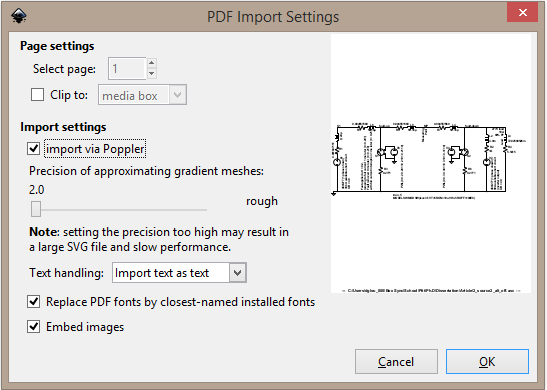
- Once imported, right-click on image and select "Ungroup"
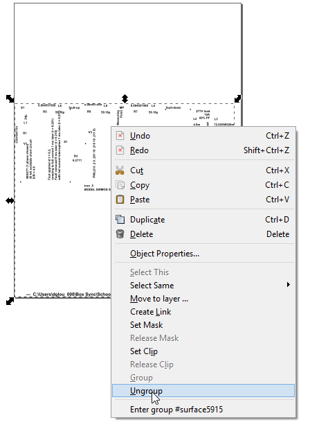
- Click away to deselect, then rubber band around any items you don't want (text, other images, etc.) and delete those items.
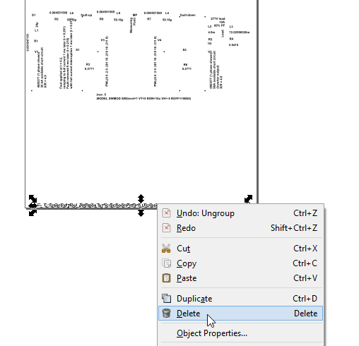
- Save your cleaned up image as .eps (encapsulated postscript)
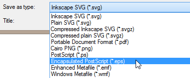
I've found that .eps works the best when importing graphics into Lyx (LaTeX front end editor).
Good luck!
#42
3-Phase Power / Excel Phasor Diagram Builder
Last post by Dave Loucks - September 25, 2015, 10:59:13 AM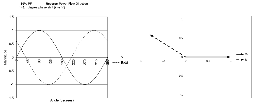
I found that I needed to draw phasor diagrams for some IEEE papers I was writing that would render properly when typeset. I've included another article on how to export a scalable vector diagram, but here I just wanted to talk about the program I wrote that creates the diagram in the first place.
Previously I had simply used a drawing program (like PowerPoint or Inkscape), but I wanted a diagram that was accurate to the degree.
So, I created this Excel program. To use:
- Cell B4: Enter in desired power factor
- Cells B7-B17: Enter in any harmonic percentages
- Cell B19: Enter power flow direction (+/-)
- Cells Y2-Y3: Enter any scaling factors
If these are left at the defaults of "1" for both voltage and current, each vector will be the same length (1). - Click to select either diagram, and select File->Print. Only the selected diagram will print.
If you are wanting to publish these diagrams, print to a PDF format and then refer to this other article on how to extract the diagram in a scalable vector format suitable for typesetting.
I've also added a 3-phase phasor diagram builder. Just plug in the 3 phasor's names (Ia, Va, Vab, etc.), the magnitude and phase angle (in degrees) and you will plot the 3 phasors.
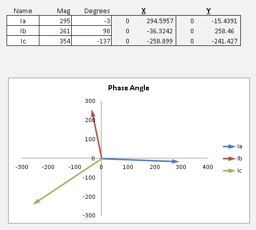
Here's a video that explains how to use the 3-phase phasor diagram builder: http://pps2.com/v/s/1/tpd.php
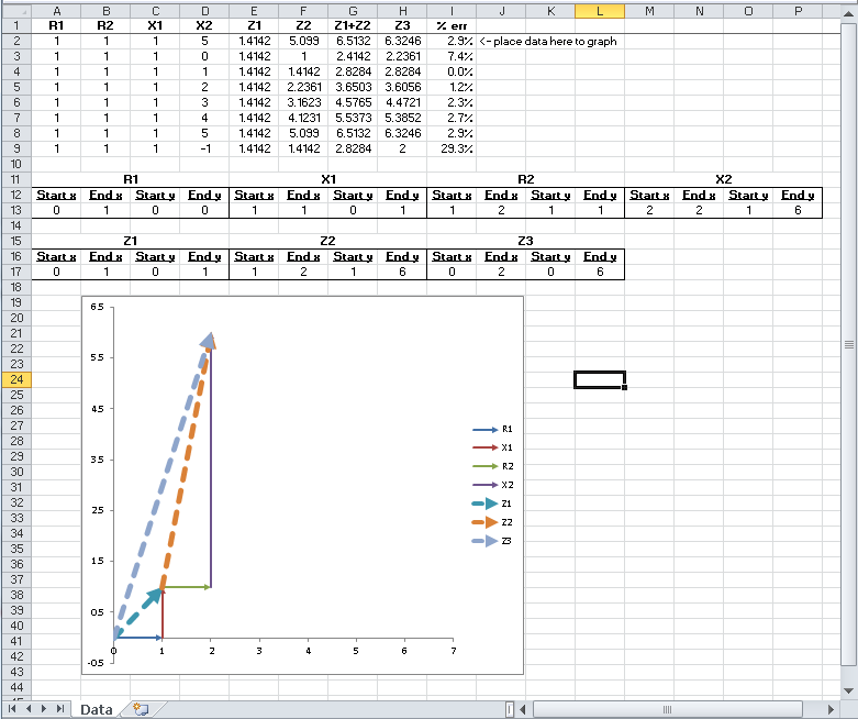
Thirdly, if you are interested in creating stacked vector diagrams (vector connected to end of other vector), I wrote another article where I show how to do that (article actually on comparing differences between summed absolute values of impedance versus summing real (R) and reactive (X) components and I show graphically the differences using stacked vector diagrams). Click to jump to that other article (or click on spreadsheet image immediately below): http://pps2.com/smf/index.php?topic=46.msg53#msg53
#43
Profibus / Profibus MINT (PMINT)
Last post by Dave Loucks - August 19, 2015, 04:01:05 PM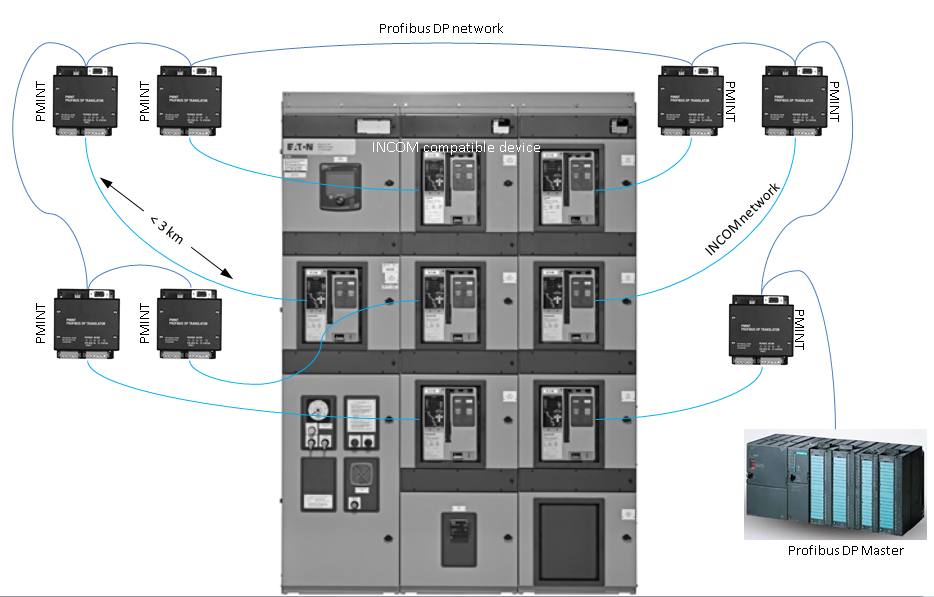
The Profibus DP MINT (PMINT) is a 1-to-1 converter device. You will need one PMINT for every legacy INCOM device (e.g. circuit breaker trip units) that you wish to connect to a Profibus network.
For more information you can download the 66A7686 Instruction Leaflet (IL) from the Moeller (a division of Eaton) web site.
http://www.moeller.pl/Documentation/AWB/AWB1230-1621.pdf
For your convenience, a copy of this IL is attached below.
#44
Modbus / Decoding PRODUCT ID Register (...
Last post by Dave Loucks - August 03, 2015, 05:50:59 PMVERY IMPORTANT
A request to read the Modbus MINT PRODUCT ID must always start at the PRODUCT ID 406255 register (underlying address 625410 or 186E16). You can still read a block of registers (i.e. read other registers in the same message along with the PRODUCT ID register), but you must always start reading at the 406255 register.
Correct Example:
Modbus Address: 1
Starting Register: 406255 (register number) or 625410 (address)
Number of Registers to Read: 4 (collects both PRODUCT ID and Frequency (Hz))
The mMINT will return four 16-bit registers, the first two being the PRODUCT ID of the INCOM device associated with Modbus address 001 (which could be either a device with INCOM address 001 or could be something else if the mMINT routing tables are used to remap Modbus-to-INCOM addresses) and the second two the frequency as a 32-bit integer scaled by 10 (divide 32-bit number by 10 to get actual frequency).
Incorrect Example:
Modbus Address: 1
Starting Register: 406253 (register number) or 625210 (address)
Number of Registers to Read: 6 (collects Power Factor, PRODUCT ID and Frequency)
The mMINT will return six 16-bit registers, with the first two being the power factor, the next two being the PRODUCT ID and the last two being the frequency. Because you didn't request PRODUCT ID as the first register in the table, the value returned will be INCORRECT.
Decoding Fast Status
The data returned in PRODUCT ID is the data returned using the INCOM "Fast Status" message. You can read about the INCOM Fast Status message in the IMPACC protocol guide: http://www.eaton.com/ecm/groups/public/@pub/@electrical/documents/content/1030709222496.pdf#page=33
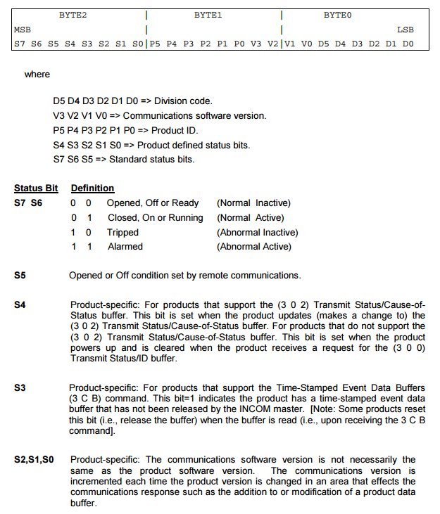
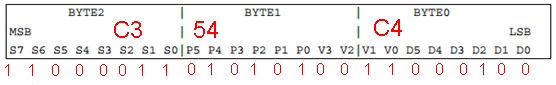
You'll notice that there are three 8-bit bytes returned, which contain a total of 24-bits. Because Modbus registers are 16 bits long, you need two registers or 32 bits. There won't be anything in the upper half of the second register (BYTE3 as described in INCOM protocol manual and how I display it in my Excel program).
Notice that inside those 24 bits you see letters S, P, V and D with numbers after them.

"S" are status bits. These describe the state of the device (open, closed, trip, alarm, etc.). You see that bit S7 and S6 define whether the device is open, closed, tripped or alarm (for example, in a trip unit like the Digtrip 1150, alarm corresponds to a long delay pickup... you are going to trip if the current stays at this level). S7 and S6 are the most significant bits of Byte 2 of the reply returned. Note: the meaning of these bits can change depending on the type of device providing the Fast Status ... e.g. a trip unit versus a meter versus a transfer switch controller.
For example, if you look at the INCOM guide for the DT1150: http://www.eaton.com/ecm/groups/public/@pub/@electrical/documents/content/il17384c.pdf#page=136
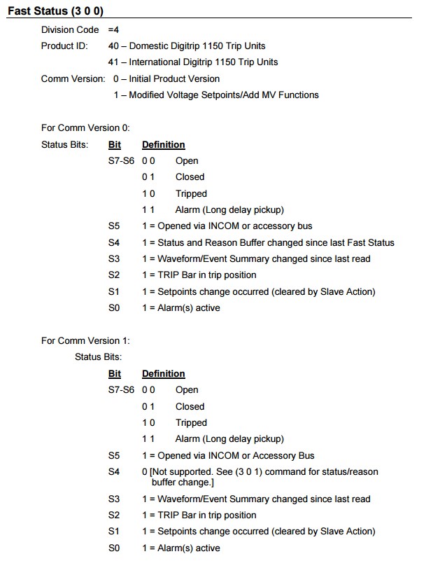
So you see that S0-S5 provides additional information. But you also see that the meaning of S4 differs depending on whether you have COMM VERSION 0 (bits V3-V0 are all zero) or if you have COMM VERSION 1 (bits V3-V1 are zero and V0 is one).
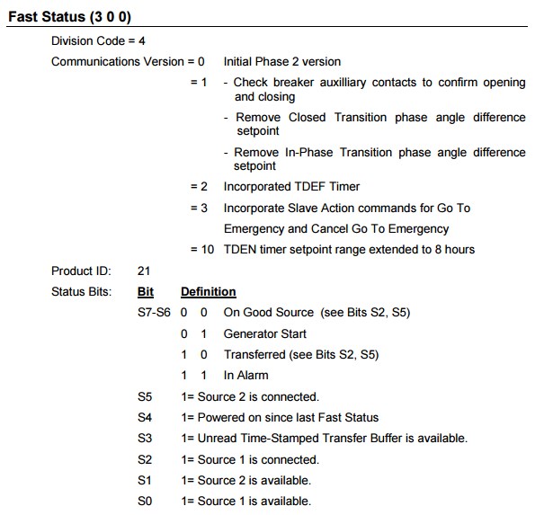
Here's another example... an ATC-600.
Checking out the ATC-600 (also known as the IQ Transfer II) you see from: http://www.eaton.com/ecm/groups/public/@pub/@electrical/documents/content/il17384f.pdf#page=61 that the Fast Status (and therefore what is returned in the PRODUCT ID register in the Modbus MINT is as follows:
Using the mMINT Excel program, and reading the PRODUCT ID register, you might get something that looks like this:

We see that the values returned are:
BYTE0 / B0 = 196 (C416)
BYTE 1/ B1 = 84 (5416)
BYTE 2 / B2 = 195 (c316)
Converting these hexadecimal values into binary (to see the individual bits) we have the following:
Now you can segregate the bits into their groups. Starting with the Division Code, we see the following:
BYTE0:
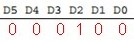
Converting this Division code from binary to decimal we have 4 ... the correct value
Now looking at the Communication Version we take the top 2 bits of BYTE0 and the bottom (least significant) 2 bits from BYTE1:

Converting this Communications Version from binary to decimal we have 3. From the list above:
Now looking at the remaining bits in BYTE1
BYTE1:

Converting this PRODUCT ID from binary to decimal we have 16+4+1 = 21 ... the correct value
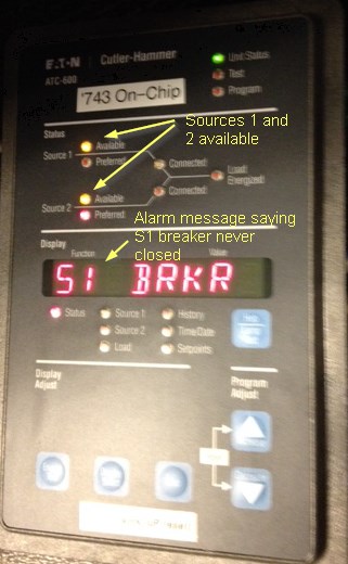
Now finishing with BYTE2:

Both bits S6 and S7 are on, so we are in alarm:
 Only bits S0 and S1 are on, so both sources are available.

Sure enough, when we look at the faceplate of the ATC, that is what we see... both sources are available and we are in alarm!
A request to read the Modbus MINT PRODUCT ID must always start at the PRODUCT ID 406255 register (underlying address 625410 or 186E16). You can still read a block of registers (i.e. read other registers in the same message along with the PRODUCT ID register), but you must always start reading at the 406255 register.
Correct Example:
Modbus Address: 1
Starting Register: 406255 (register number) or 625410 (address)
Number of Registers to Read: 4 (collects both PRODUCT ID and Frequency (Hz))
The mMINT will return four 16-bit registers, the first two being the PRODUCT ID of the INCOM device associated with Modbus address 001 (which could be either a device with INCOM address 001 or could be something else if the mMINT routing tables are used to remap Modbus-to-INCOM addresses) and the second two the frequency as a 32-bit integer scaled by 10 (divide 32-bit number by 10 to get actual frequency).
Incorrect Example:
Modbus Address: 1
Starting Register: 406253 (register number) or 625210 (address)
Number of Registers to Read: 6 (collects Power Factor, PRODUCT ID and Frequency)
The mMINT will return six 16-bit registers, with the first two being the power factor, the next two being the PRODUCT ID and the last two being the frequency. Because you didn't request PRODUCT ID as the first register in the table, the value returned will be INCORRECT.
Decoding Fast Status
The data returned in PRODUCT ID is the data returned using the INCOM "Fast Status" message. You can read about the INCOM Fast Status message in the IMPACC protocol guide: http://www.eaton.com/ecm/groups/public/@pub/@electrical/documents/content/1030709222496.pdf#page=33
You'll notice that there are three 8-bit bytes returned, which contain a total of 24-bits. Because Modbus registers are 16 bits long, you need two registers or 32 bits. There won't be anything in the upper half of the second register (BYTE3 as described in INCOM protocol manual and how I display it in my Excel program).
Notice that inside those 24 bits you see letters S, P, V and D with numbers after them.
"S" are status bits. These describe the state of the device (open, closed, trip, alarm, etc.). You see that bit S7 and S6 define whether the device is open, closed, tripped or alarm (for example, in a trip unit like the Digtrip 1150, alarm corresponds to a long delay pickup... you are going to trip if the current stays at this level). S7 and S6 are the most significant bits of Byte 2 of the reply returned. Note: the meaning of these bits can change depending on the type of device providing the Fast Status ... e.g. a trip unit versus a meter versus a transfer switch controller.
For example, if you look at the INCOM guide for the DT1150: http://www.eaton.com/ecm/groups/public/@pub/@electrical/documents/content/il17384c.pdf#page=136
So you see that S0-S5 provides additional information. But you also see that the meaning of S4 differs depending on whether you have COMM VERSION 0 (bits V3-V0 are all zero) or if you have COMM VERSION 1 (bits V3-V1 are zero and V0 is one).
Here's another example... an ATC-600.
Checking out the ATC-600 (also known as the IQ Transfer II) you see from: http://www.eaton.com/ecm/groups/public/@pub/@electrical/documents/content/il17384f.pdf#page=61 that the Fast Status (and therefore what is returned in the PRODUCT ID register in the Modbus MINT is as follows:
Using the mMINT Excel program, and reading the PRODUCT ID register, you might get something that looks like this:
We see that the values returned are:
BYTE0 / B0 = 196 (C416)
BYTE 1/ B1 = 84 (5416)
BYTE 2 / B2 = 195 (c316)
Converting these hexadecimal values into binary (to see the individual bits) we have the following:
Now you can segregate the bits into their groups. Starting with the Division Code, we see the following:
BYTE0:
Converting this Division code from binary to decimal we have 4 ... the correct value
Now looking at the Communication Version we take the top 2 bits of BYTE0 and the bottom (least significant) 2 bits from BYTE1:
Converting this Communications Version from binary to decimal we have 3. From the list above:
Now looking at the remaining bits in BYTE1
BYTE1:
Converting this PRODUCT ID from binary to decimal we have 16+4+1 = 21 ... the correct value
Now finishing with BYTE2:
Both bits S6 and S7 are on, so we are in alarm:
Only bits S0 and S1 are on, so both sources are available.Sure enough, when we look at the faceplate of the ATC, that is what we see... both sources are available and we are in alarm!
#45
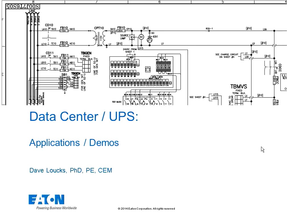
3-Phase Power / Power Systems UPS
Last post by Dave Loucks - June 10, 2015, 03:45:55 PMThe presentation below covers some of the important topics that are top of mind for data center owners and operators today.
The audio for the presentation (YG_Loucks_Day2_UPS.pptx) attached below can be downloaded from here.
I recently updated the presentation to include new material (2- and 3-level converters, etc.) and created a voiced-over presentation that you can play by clicking on the image below. The updated presentation that goes with this is also attached below (YG_Loucks_Day2_UPS_c.pdf).
- UPS multi-mode / ECO-mode (ESS)
- Financial analysis
- VMMS
- Power Supply Unit (PSU) Tested Performance
- Coordination and Timing of switching (Eco-mode vs STS vs PSU hold-up timing
The audio for the presentation (YG_Loucks_Day2_UPS.pptx) attached below can be downloaded from here.
I recently updated the presentation to include new material (2- and 3-level converters, etc.) and created a voiced-over presentation that you can play by clicking on the image below. The updated presentation that goes with this is also attached below (YG_Loucks_Day2_UPS_c.pdf).
#46
3-Phase Power / Power Systems Load Flow and PF...
Last post by Dave Loucks - June 10, 2015, 03:26:54 PMPresentation attached below is an overview of the following topics:
Audio of this presentation can be downloaded here.
A later version (YG_Loucks_Day2_LoadFlow_PFC_b.pdf) of the presentation is also attached. Click on the video below to see my presentation of this material.
- Load flow - voltage drop
- Motor starting
- PFC
- Resonance
Audio of this presentation can be downloaded here.
A later version (YG_Loucks_Day2_LoadFlow_PFC_b.pdf) of the presentation is also attached. Click on the video below to see my presentation of this material.
#47
3-Phase Power / Power Systems Protection and C...
Last post by Dave Loucks - June 10, 2015, 10:56:40 AMOverview covering:
Presentation is attached below and the audio of the earlier version of the presentation can be downloaded from here.
The latest presentation is also attached (YG_Loucks_Day2_Protection_Coordination.pdf) and you can view a presentation of me presenting this later version by clicking on the link of the image of the video immediately below.
- Selective Coordination vs Series Rating
- Time Current Curve differences by equipment type
- Switchboard vs Switchgear
- NEC Article 240.87
- Zone Selective Interlocking
- Differential Protection
- Arc Reduction Maintenance System (ARMS)
- Light Sensing Solutions
Presentation is attached below and the audio of the earlier version of the presentation can be downloaded from here.
The latest presentation is also attached (YG_Loucks_Day2_Protection_Coordination.pdf) and you can view a presentation of me presenting this later version by clicking on the link of the image of the video immediately below.
#48
3-Phase Power / Power Systems Rules of Thumb
Last post by Dave Loucks - June 10, 2015, 10:26:42 AMThis presentation discusses:
You can download the PDF of the presentation attached below. Audio of the presentation can be downloaded from here.
You can also download a later version of this presentation (YG_Houston_2016_power_sys_analysis.pdf) that contains some different information, but doesn't exactly track the audio file. I'll be uploading the audio for this newer presentation at a later time.
- Transformer review (including deriving internal R and X from loss data)
- Fault calculations
- Per Unit theory and practice
- Asymmetric Faults
- X/R rules of thumb
You can download the PDF of the presentation attached below. Audio of the presentation can be downloaded from here.
You can also download a later version of this presentation (YG_Houston_2016_power_sys_analysis.pdf) that contains some different information, but doesn't exactly track the audio file. I'll be uploading the audio for this newer presentation at a later time.
#49
3-Phase Power / MV Transient Analysis - Missio...
Last post by Dave Loucks - April 29, 2015, 09:58:13 AMMV vacuum breakers combined with low BIL devices (like dry-type transformers) can have problems. Here's a presentation that was prepared for the Critical Power 2015 conference in Milwaukee that discusses them.
http://pps2.com/v/1/cp.php
You can download a copy of the presentation below.
http://pps2.com/v/1/cp.php
You can download a copy of the presentation below.
#50
Modbus / Modbus MINT (Modular INCOM Net...
Last post by Dave Loucks - March 04, 2015, 02:20:16 PM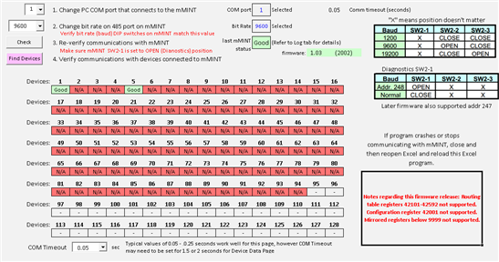
I've attached an Excel 2010 (Windows) spreadsheet that, if you have Excel 2010 (or later?), it can be used to communicate with a Modbus MINT via a COM port.
I wrote the code to send and receive Modbus messages from within Excel using Excel's scripting language, VBA, and to decode the data returned to make it easier to interpret. No more MODSCAN needed!
Here's an 18 min screencast tutorial I created that explains how this program works.
I'm adding features over time, so check back to learn about upgrades. I'm also including earlier (simpler) versions since if all you want is the Modbus VBA code, you won't want to weed through bigger and bigger programs to snip out a Modbus Read or Modbus Write algorithm!
Revision list (major changes)
VBA-comms9
- Now displays firmware year correctly for all mMINT firmware releases to date.
- Detects certain mMINT user configuration errors. "Fix It Now" buttons appear when these problems are detected. The user can chose to press this button to reconfigure mMINT configuration to correct values.
VBA-comms10
- Added support for sending Loopback Diagnostic codes to addresses other than 248. This is important since (as shown in Table 6 in the mMINT Instructional Leaflet), sub-function codes 21 and 22 (slave INCOM BCH error count and slave INCOM overrun count, respectively) only have meaning for INCOM devices.
- Changed Diagnostic counters so they could be reset to zero after pressing the "Send Reset" button on the mMINT tab.
- The "Start Here" check for the mMINT now also reads the firmware version and displays both it and the firmware year following the pressing of the "Check" button.
- Changed how the firmware version and revision was displayed. Now forced the revision to be a 2-digit number by inserting a leading zero into the revision for any revision less than 10. Example: version 1, revision 3 would now be displayed as V1.03 instead of V1.3 (as it would have been shown in prior versions of this program.) This was done to match the look of the version sticker placed on the mMINT case by manufacturing.
- (mMINT tab) Changed descriptive text above the "Write Routing" button explaining that to write changes you must press both "Write Config" (to update configuration registers 42001-42003) AND "Write Routing" (routing registers 42101 - 42592). While it may have been clear you needed to press both buttons to update both sets of settings, the text was modified to clarify further.
- Program now checks mMINT firmware and displays appropriate error messages about unavailability of routing and/or configuration table programmability. Releases prior to V1.05 did not support either, nor did it include the mirrored registers below 9999. Earlier releases placed data in registers above 9999 which some Modbus masters could not access. Releases prior to V1.06 did not support mMINT address 247. Releases prior to V1.10 did not support ATC-300 transfer switch controller. All these idiosyncrasies are now flagged to the user, hopefully clarifying why their (older) mMINT doesn't seem to have the functionality described in the (latest) instructions found on the web.
VBA-comms11
This is a fairly extensive update to the code. As such, all this extra code is making this program more unwieldy to follow, so this is the first version that I've switched off viewing of the underlying code. Shouldn't be a problem if all you wanted were the Modbus read/write commands. You can see those in the earlier versions!
Screencast tutorials on new features:
Here's the list of upgrades to this version:
- Includes an example of a simple "Backup and Restore" functionality to allow a user to send their data to a cloud based storage for safekeeping.
- Activation feature included to serialize each copy of the program.
- Added code to troubleshoot if not able to configure COM port. In the past, program would simply not communicate without providing any indication of the reason for the failure.
- Checkbox included ("Extended error logging") to enable/disable the logging of COM port configuration errors. If this checkbox is checked (is by default), then failures to configure COM port are written to log file with additional descriptive text explain the reason for the failure.
- Added additional diagnostics to detect if modem or line driver is in loopback or echo mode. A warning given for the user to check their settings to insure the system is set to 2-wire mode. Converters/modems/line drivers properly set in 2-wire mode mute their receivers when they are transmitting so they don't hear a copy of their own transmission.
- Added additional diagnostics to detect if the COM port selected is in use. (One potential situation is if this program crashes during communications. If so, the program won't have signaled the Windows operating system that it is finished using the COM port and to Windows, it will still be in use. A subsequent attempt to reconnect using the same port will be rejected by Windows as that port will be considered to still be in use. The fix is to close and reopen Excel.)
- Fixed bug that could cause the COM routine to hang in the particular case where the program was interrupted (or crashed) during communications. The system would be left in a state where a subsequent attempt to communicate would result in the receiver waiting indefinitely for a response to a message. True Modbus assumes the end of a message has been received if no character is received after waiting 3.5 character times and hearing no new data. While program functionality worked properly prior to a crash, it wasn't immediately obvious (due to my attempt to more gracefully recover after a crash) to the user that the program had crashed. I now alert the user by giving more details in the log file, advising that the program should be shut down and restarted to resolve this problem.
- Device Data tab now include a check box that activates displaying the data retrieved from the devices connected to the mMINT as hexadecimal in addition to decimal.
- Added new color code (orange) to the background of each value read from the mMINT, now in addition to green (valid response) and red (invalid/failed Modbus message response). Orange means that a valid response was heard but it exactly matched the message sent. This is normally an indication of an improperly configured 485 line driver/converter or modem (likely set for 4-wire rather than 2-wire mode but connected on a 2-wire network). However, this can occur normally in the one case of the Modbus Loopback function. The mMINT uses the Modbus Loopback function to interrogate certain internal mMINT registers (these are status registers internal to the mMINT and outside the normal Modbus register memory map). Since it is perfectly possible for a response to match the request (occurs when the response says there is a zero in the register), it could also indicate an echo. If at least some of the data is returned as green, then it is likely not an echo and the orange coded fields can safely be assumed to be "green"
- Besides adding the color code for the loopback messages, also seeded the loopback request with a non-zero value in one of the overhead bytes. Now, if the mMINT responds correctly, the reply will more than likely overwrite that reply with a different value and the request and the reply won't match. That tells the program that there isn't a modem loopback returning a reply, but it is a real Modbus device. The field will be color coded green instead of orange. If, in the unlikely but possible event that the reply includes that seeded value, the program will have no way to know if that particular message was an echo of the request or if it was an actual reply with real data (that just happened to match the seed value put in the request). In this case, the response will be color coded orange. However, as mentioned above, if the modem is in loopback mode, ALL responses will be echoes of the requests, not just one. Therefore if ANY of the other responses are green, then we know that the modem is not in loopback (or a 2-wire system is set to 4-wire mode, for example).
- Discovered that the mMINT could get into a mode where it would respond to messages addressed to 248 (or 247) and would pass-through requests for addresses 1-246, but would not translate the response from those INCOM messages into Modbus. With no reply from the mMINT, the polling program would assume the INCOM devices 1-246 went off line. However, when examining the appropriate INCOM device's Tx and Rx LEDs, it was clear that an INCOM reply was being sent - the mMINT just chose to not translate this into a Modbus message and forward to the polling device! The solution was to send a sequence of mMINT reset messages listed in Table 6 of the Instruction Leaflet (IL). Now, when pressing the "Check" button, the program not only reads firmware revision information, it also sends loopback subfunction codes 10 (clear slave counters), 20 (clear UART counters), 29 (remove INCOM devices), and 30 (reset INCOM routing addresses).
- Prior to downloading "Selected Cloud Values" to mMINT, a validity check is performed (basically are the values integers in the proper range?) prior to downloading.
- Added new tab "Control" that issues INCOM Slave Action messages through mMINT to INCOM devices
- Backup-Restore tab: If one user logs in and retrieves a file listing for their account, then opens the window to select a file to upload (doesn't matter whether they do or don't upload) and then a second user logs in and retrieves a listing of the stored files for that second account, when the second user attempts to view the available files they will see the file listing for the first user. Fix: Close Excel spreadsheet to completely log out the first user. Fixed in V0.12.
- Fixed a major bug where data copied from the cloud was written to the mMINT registers offset down by two. In other words, if the value was supposed to have been written into mMINT register 42103 and 42104, it instead was written to 42101 and 42102. Fixed in V0.12
- Fixed bug where the firmware revision was stored properly in its correct location in the cloud database, but also incorrectly overwriting the firmware month and day. Fixed in 0.12.
VBA-comms12
- Modified code to use new database (database SQL injection protection algorithms changed)
- Added new error messages when attempting to store data to cloud if DLM system is offline.
- Added new error message if attempting to download a blank listing from the cloud database.
- Added status message. After copying file from cloud the program displays a message that it is ready to write selected values to mMINT. In other words, the program is waiting for you to press the 4th button marked Write Selected Cloud Values to mMINT.
- Switched off PHP error display (improve security)
- When registering as a new user, enlarged the Comments box (made it support multiple lines ... use <Shift>-<Enter> to create new line) on the new user registration form. Also included a character counter so user knows how many of the remaining 1000 characters for this comment field are available.
- Added missing label Device over columns F & G, row 11. Also changed labels over row 12 to say decimal and hex.
- Fixed bug in Backup-Restore tab where if one user logged in with one set of credentials, downloaded a listing (but didn't choose a file) -- if then a second user logged in with a different set of credentials and downloaded a different list of files -- the system would present the files from the first user, not the second.
- Added status messages to display if a user tries to register a username/email that has already been registered (but is awaiting authorization by an admin).
- Fixed a major bug where data copied from the cloud was written to the mMINT registers offset down by two. In other words, if the value was supposed to have been written into mMINT register 42103 and 42104, instead incorrectly it was written to 42101 and 42102.
- Fixed bug where the firmware revision was stored properly in its correct location in the cloud database, but also incorrectly overwriting the firmware month and day.
VBA-comms13
- Discovered that in the 1.10 version of the mMINT firmware if attempting to read PRODUCT ID (register 406255 or address 6254) as part of a larger block of data (such as attempting to read registers 406145-406262), invalid data would be returned. The solution was to issue a read register command starting with the PRODUCT ID register 406255 (address 6254) by itself. When reading only that register (or when that is the first register of a block of registers, the data returned would be correct.
VBA-comms14
- Fixed the problem where the PRODUCT ID register still wasn't updating correctly (too little regression testing on V0.13... that's what happens when you rush a fix!).
VBA-comms15
- Decodes the PRODUCT ID 32-bit register pair (406255-406256) and populates S(tatus), D(ivision), P(roduct ID), and V(communication firmware version). From the "Start Here" tab, after you have clicked on the "Find Devices" button, just click on the cell associated with any found device. The decoded values from the PRODUCT ID register pair will be displayed at the top of the spreadsheet.
In the screenshot below P=21 (which according to https://www.eaton.com/ecm/groups/public/@pub/@electrical/documents/content/il17384f.pdf#page=61 means this is an automatic transfer switch controller), bits 6 & 7 of the Status register (S67) = 3 (or 1 1 binary which according to that same link means the ATC is in alarm), bits 0 through 5 of the Status register (S05)=3 (or 1 1 binary, which means that both sources feeding into the transfer switch are available), V=3 which means Comm firmware version 3 is installed and finally D=4 which is an internal designation for an Eaton business division.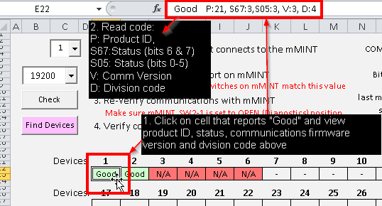
NOTE: for more information on decoding the PRODUCT ID register, refer to the article immediately below.
VBA-comms16
- Includes a new feature that allows "pinging" individual Modbus register addresses to see if they are valid.
This feature is useful when using the mMINT "zero-fill" setting. With zero-fill, registers that you request from the mMINT for a particular device will return zeros (rather than errors) if you attempt to read a register that is not available for that device (example: attempting to read line voltage on a Digitrip 520).
The trouble is, you have no way of knowing which registers are returning real zero values and which are returning zeros to tell you that register isn't supported.
Now, with this feature, you can switch off zero fill (see tutorial video) and ping each register in question. The program is pretty manual right now, but if you get an error when you ping a Modbus register, well you know that device doesn't support a read from it!
Check out this tutorial video on using this new feature.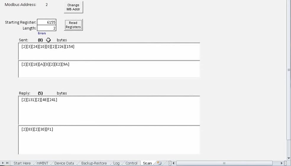
VBA-comms17
- Includes a new feature that allows monitoring traffic over a serial network by using something called "Eavesdrop mode". While version 16 added the ability to send and receive messages and watch the bytes sent and received from this program, version 17 adds a new feature to listen to a serial network and copy the traffic (similar to how WireShark does this on an Ethernet network).
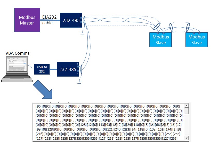
The data is just copied raw. No interpretation of the data is made.
To use: Make sure you have selected the right serial port (COM1, 2, etc.) and bit rate (only 1200, 9600 and 19200 are supported in this version) from the Start Here tab in the spreadsheet.
Then just select how many bytes you want to collect (10-10000) and press the "Eavesdrop" button.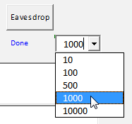
Data will be retrieved until at least that many bytes have been captured. The number of bytes collected so far will be displayed as "Block: xxx" (where xxx are the number of bytes captured so far). You can press stop to halt collection. No data is shown in the windows until the last byte has been collected (or after the stop button is pressed).
The received data will then be displayed both in decimal and hexadecimal formats. You can copy data from either window and paste to a document or email.
Note: No interpretation of the data collected is made. However, V18 is planned to recognize and automatically parse Modbus messages (e.g. Is a particular byte shown on the screen from the master or a slave? If latter, which? Is the message a read or write and to what register, bit or I/O is the message addressing and what value was transmitted to/from that register, bit or I/O? Was the message completed successfully?, If not, what was the error and possible fix?, etc.)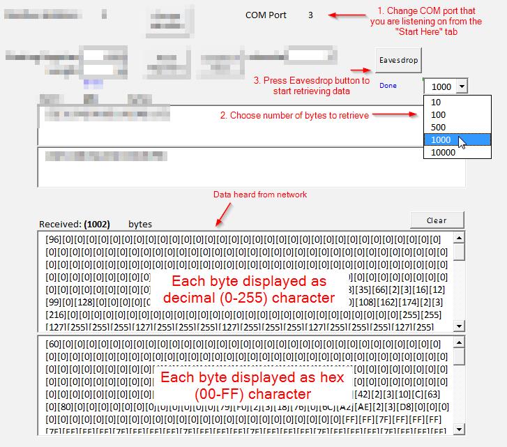
VBA-comms18
- Bug fix: For COM ports > 2 might give error code 9 and report the port was not available even if port was available
- Bug fix: Error when pressing "Send Reset" button in mMINT tab.
VBA-comms19
- Bug fix: For bit rates other than 19.2 kbps, the VBA_Comms could prematurely timeout and report a bad response. Now fixed.
VBA-comms20
- Rewrote it to remove ActiveX controls (buttons, combo boxes, etc.) and replace with Form controls. Some users were reporting problems with running Active X
VBA-comms21
- Minor bug fix. Can now reset mMINT Table 6 registers assigned to each INCOM slave device.
VBA-comms22
- Added support for use on 64-bit Excel.
Where are the previous version of this program?
This forum software places limits on the number and maximum size of files that can be attached to an article. Previous versions of the program can be downloaded from https://pps2.com/files/mm/