News:

Calling all communications systems experts - please share your knowledge here!

Main Menu
Menu

Show posts

This section allows you to view all posts made by this member. Note that you can only see posts made in areas you currently have access to.

Show posts Menu

Topics - Dave Loucks

#21
3-Phase Power / Low Voltage Utility Networks
May 10, 2016, 11:48:30 AM
The AC secondary network system have been used for many years (since 1920s!) to distribute electric power in the high-density, downtown areas of cities, usually in the form of utility grids. Modifications of this type of system make it applicable to serve loads within buildings.  The major advantage of the secondary network system is continuity of service. No single fault anywhere on the primary system will interrupt service to any of the system's loads. Most faults will be cleared without interrupting service to any load.  In fact, unlike "conventional" circuit breaker protected circuits, the network is designed so that a fault will 'burn clear' without interrupting current. 

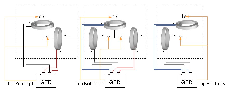
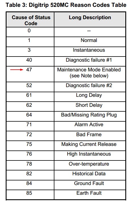
The primary protective device used in a network is called the network protector (NWP).  Because the NWP is not designed to open during a fault downstream, protective relaying is different than on conventional systems connected to loop or main-tie-main systems.

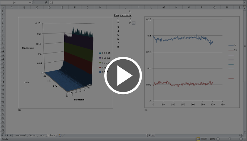
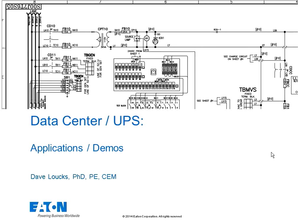
I created a 30 minute narrated PowerPoint video that explains some of how a LV secondary network functions.

You can learn more by visiting the LV secondary network site at Eaton.com or by reading the power distribution engineering section within the Consulting Application Guide (CAG).  Secondary networks begins on page 14 (as of the date of this entry).
#22
3-Phase Power / Harmonic Trend Viewer
April 05, 2016, 01:00:51 PM
Starting with firmware version 13.3.5.7 on the PXM 4/6/8K Meters a new feature was added that offers the option to generate a harmonic capture .csv file (magnitudes only H1-H128) with matching waveform at every Load Profile interval. The capture is based on a 60 cycle waveform taken at the beginning of the Load Profile interval.

Since the data is stored in a comma separated variable file format, it is easy to open in Excel and view.  However since each row is a different time of a different harmonic, displaying this output file to show, for instance, the 3rd harmonic plotted over time would require sorting the data by harmonic number and then by time.

To simplify this work, we've created a spreadsheet that does this sorting for you.  As a bonus, a 3D and 2D time series graphs are included.

Check out my quick tutorial on how to use this program (or click on the video image below).
#23
3-Phase Power / Z vs R + jX fault calculations
February 02, 2016, 04:51:22 PM
A very acceptable first-pass approximation of determining fault current is to use impedance (Z), or more typically per unit (%Z).

However, when two or more impedances are connected in series, the sum of the absolute values of the separate impedances isn't exactly the same as the sum of the real and reactive parts of the impedance.  This can be shown graphically.


Here it is visually evident that the sum of the two impedances does not equal the actual series impedance, or mathematically:

but since:

and:

then:


Click on the image of the spreadsheet below to play back a voiced-over narration describing this issue, plus I explain how to use a spreadsheet tool to visualize the results.

Narrated explanation: https://pps2.com/v/1/ZvRX.php


Another thing that might be useful from this video is I show how to calculate and draw these stacked vector plots within Excel.  For more detail on creating phasor plots, refer to this separate article (Excel Phasor Diagram Builder)

Download the spreadsheet from the link below.
#24
3-Phase Power / Spoof Video - Basic Electricity
January 09, 2016, 04:33:48 PM
Dan Carnovale and I recorded a remake of a famous Cutler-Hammer spoof video entitled "Basic Electricity".  The same production company was used to make the "real" videos for the Eaton Power Systems Experience Center in Warrendale Pennsylvania, so while the video was a spoof, the production values were quite good.

Enjoy.

#25
3-Phase Power / Differential Ground Fault Protection
December 04, 2015, 08:46:29 AM


Differential ground sensing is useful in several situations:
  • Multiple, grounded sources on 3-phase, 4-wire system switched with 3-pole devices (neutral is not switched)
  • Current flow can reverse (this makes using ZSI more difficult to apply)

The following narrated screencast discusses how a differential ground system can be applied to isolate ground faults to within electrical switching systems (switchboards, switchgear) or even buildings.  This design does not require current transformer (CT) wiring to extend outside the zone of protection.

Narrated Screencast Differential GF Sensing: http://pps2.com/v/1/dgfs.php

The simulations shown in this model are based on LTSPICE.  More information on LTSPICE is available from http://www.linear.com/designtools/software/.  I've created another screencast that provides some basic information on how to use LTSPICE to run the simulations shown for this differential ground fault simulation.

Narrated Screencast LTSPICE: http://pps2.com/v/1/lts.php

Download LTSPICE simulation files: https://app.box.com/s/wib5s1biu901mhlungqc1fs611zt5iay/url]

Special Note:
Occasionally a different kind of differential protection will be necessary.  Refer to the following Eaton application notes for more information:
  • [url=http://www.eaton.com/ecm/groups/public/@pub/@electrical/documents/content/wp027003en.pdf]Ground fault isolation with loads fed fromseparately derived grounded sources[/url]
  • [url="http://www.eaton.com/ecm/groups/public/@pub/@electrical/documents/content/wp027004en.pdf"]Grounding methods in missioncritical facilities[/url]
#26
Harmonic summation and cancellation can be a tricky subject.  For example, why do 3rd harmonics sum in the neutral but cancel phase-to-phase?

To answer those questions, I created an Excel spreadsheet (attached at bottom of this article) that allows you to dial in various harmonics and see just what happens in the neutral as well as when measuring phase-to-phase voltage on two harmonic laden phases.


HINT: Summation and cancellation of 3rd harmonics are easier to understand when we remember that they are zero sequence.  That means that each phase harmonic is in-phase with each other.

Have fun!

Here's a quick screencast tutorial: https://pps2.com/v/1/hmc.php
#27
INCOM / IMPACC / Digitrip 520MC Communications
October 02, 2015, 02:11:27 PM
I've attached the most up-to-date version of the INCOM communication protocol description I have for this product. 

In particular, this includes the Extended Status Code (3 0 1) reply (code 47) to retrieve whether the breaker is in ARMS mode (Arcflash Reduction Maintenance System) or not.


#28
Figure 1: Example of drawing printed as scalable vector image


Advantage is that even scaled, no evidence of loss of resolution in image

When publishing a document, you know that what looks good on your screen doesn't necessarily look good printed, or worse, blown up to a wall size document.  For highest quality, scalable vector graphics look better than raster (scanned) images.  Scalable vector graphics are defined by mathematical equations, so they don't lose resolution when zoomed.

The easiest way I found of creating a vector graphic from inside programs like Excel or PowerPoint is to save the file as a PDF. 

However, some (many?) programs can't import a graphic image in PDF format.  Plus, even if you could, how do you extract just the graphic from a page that might also have a lot of text?

For that I use Inkscape.

The procedure I found that works best is the following:

  • From Inkscape, open the PDF file that you previously saved or printed from Excel, PPT, etc.
  • In Inkscape, from the File->Open menu, check the checkbox "import via Poppler"
  • Once imported, right-click on image and select "Ungroup"
  • Click away to deselect, then rubber band around any items you don't want (text, other images, etc.) and delete those items.
  • Save your cleaned up image as .eps (encapsulated postscript)

I've found that .eps works the best when importing graphics into Lyx (LaTeX front end editor).

Good luck!
#29
3-Phase Power / Excel Phasor Diagram Builder
September 25, 2015, 10:59:13 AM

I found that I needed to draw  phasor diagrams for some IEEE papers I was writing that would render properly when typeset.  I've included another article on how to export a scalable vector diagram, but here I just wanted to talk about the program I wrote that creates the diagram in the first place. 

Previously I had simply used a drawing program (like PowerPoint or Inkscape), but I wanted a diagram that was accurate to the degree.

So, I created this Excel program.  To use:

  • Cell B4: Enter in desired power factor
  • Cells B7-B17: Enter in any harmonic percentages
  • Cell B19: Enter power flow direction (+/-)
  • Cells Y2-Y3: Enter any scaling factors
    If these are left at the defaults of "1" for both voltage and current, each vector will be the same length (1).
  • Click to select either diagram, and select File->Print.  Only the selected diagram will print.
    If you are wanting to publish these diagrams, print to a PDF format and then refer to this other article on how to extract the diagram in a scalable vector format suitable for typesetting.
Here's a video that explains how to use this 1-phase phasor diagram builder: http://pps2.com/v/s/1/opd.php

I've also added a 3-phase phasor diagram builder.  Just plug in the 3 phasor's names (Ia, Va, Vab, etc.), the magnitude and phase angle (in degrees) and you will plot the 3 phasors.

Here's a video that explains how to use the 3-phase phasor diagram builder: http://pps2.com/v/s/1/tpd.php

Thirdly, if you are interested in creating stacked vector diagrams (vector connected to end of other vector), I wrote another article where I show how to do that (article actually on comparing differences between summed absolute values of impedance versus summing real (R) and reactive (X) components and I show graphically the differences using stacked vector diagrams).   Click to jump to that other article (or click on spreadsheet image immediately below): http://pps2.com/smf/index.php?topic=46.msg53#msg53
#30
Profibus / Profibus MINT (PMINT)
August 19, 2015, 04:01:05 PM

The Profibus DP MINT (PMINT) is a 1-to-1 converter device.  You will need one PMINT for every legacy INCOM device (e.g. circuit breaker trip units) that you wish to connect to a Profibus network.

For more information you can download the 66A7686 Instruction Leaflet (IL) from the Moeller (a division of Eaton) web site.

http://www.moeller.pl/Documentation/AWB/AWB1230-1621.pdf

For your convenience, a copy of this IL is attached below.
#31
3-Phase Power / Power Systems UPS
June 10, 2015, 03:45:55 PM
The presentation below covers some of the important topics that are top of mind for data center owners and operators today.


  • UPS multi-mode / ECO-mode (ESS)
  • Financial analysis
  • VMMS
  • Power Supply Unit (PSU) Tested Performance
  • Coordination and Timing of switching (Eco-mode vs STS vs PSU hold-up timing

The audio for the presentation (YG_Loucks_Day2_UPS.pptx) attached below can be downloaded from here.

I recently updated the presentation to include new material (2- and 3-level converters, etc.) and created a voiced-over presentation that you can play by clicking on the image below.  The updated presentation that goes with this is also attached below (YG_Loucks_Day2_UPS_c.pdf).
#32
3-Phase Power / Power Systems Load Flow and PFC
June 10, 2015, 03:26:54 PM
Presentation attached below is an overview of the following topics:

  • Load flow - voltage drop
  • Motor starting
  • PFC
  • Resonance

Audio of this presentation can be downloaded here.

A later version (YG_Loucks_Day2_LoadFlow_PFC_b.pdf) of the presentation is also attached.  Click on the video below to see my presentation of this material.
#33
Overview covering:

  • Selective Coordination vs Series Rating
  • Time Current Curve differences by equipment type
  • Switchboard vs Switchgear
  • NEC Article 240.87
  • Zone Selective Interlocking
  • Differential Protection
  • Arc Reduction Maintenance System (ARMS)
  • Light Sensing Solutions

Presentation is attached below and the audio of the earlier version of the presentation can be downloaded from here.

The latest presentation is also attached (YG_Loucks_Day2_Protection_Coordination.pdf) and you can view a presentation of me presenting this later version by clicking on the link of the image of the video immediately below.

#34
3-Phase Power / Power Systems Rules of Thumb
June 10, 2015, 10:26:42 AM
This presentation discusses:

  • Transformer review (including deriving internal R and X from loss data)
  • Fault calculations
  • Per Unit theory and practice
  • Asymmetric Faults
  • X/R rules of thumb

You can download the PDF of the presentation attached below.  Audio of the presentation can be downloaded from here.

You can also download a later version of this presentation (YG_Houston_2016_power_sys_analysis.pdf) that contains some different information, but doesn't exactly track the audio file.  I'll be uploading the audio for this newer presentation at a later time.
#35
MV vacuum breakers combined with low BIL devices (like dry-type transformers) can have problems.  Here's a presentation that was prepared for the Critical Power 2015 conference in Milwaukee that discusses them.

http://pps2.com/v/1/cp.php

You can download a copy of the presentation below.
#36
3-Phase Power / Real and Reactive Power Analysis
February 19, 2015, 02:46:03 PM
Lots of good material on the web, but I've sometimes found it confusing to understand why reactive power flow to an inductor is considered "positive", but at the same time you hear that the phase angle of inductor current is lagging (which to my ear sounds "negative").  For capacitors this is reversed (e.g. negative reactive power flow for leading current).  Anyway, I thought I'd outline a quick overview of how all this fits together.

We begin with a diagram that might be familiar to many.  It shows real power flow on the x-axis and reactive power flow on the y-axis.  Since both forward and reverse (positive and negative) real and reactive power flow is possible, there are four categories (+W/+vars, +W/-vars, -W/+vars, -W/-vars) that the diagram places in separate quadrants.  I've shown it with ABC clockwise rotation (meaning that increasing angles are increasingly "lagging" which is explained below).


The circle shows the line etched by a constant value of S at different values of 
θ
(0 to 360 degrees).

The exact same value of S (VA or apparent power) can result in a variety of different P (real) and Q (reactive) values just by changing the phase angle!

So what is the phase angle and how do you calculate it?

Let's say you just define the voltage reference right now to be 00 and you measure your current to be
θ
degrees away from that axis.  Depending on which way the angle points (above the x-axis or below) determines whether the power factor is lagging (consuming vars) or leading (producing vars), respectively.

Here's a diagram of system with where the current is lagging the voltage by 36.9 deg.


Here's where it gets somewhat tricky... the current is delayed by 36.9 degrees, which might sound like a "negative" angle, but you can see from the phasor diagram as shown that it actually is a more positive phase angle. 

sin (36.90) = 0.6


By the way, in these waveforms the peak voltage and current were both 1.  When we calculate power (whether real or reactive), we use root mean square versions of the signals.  Since we have a two nice sine waves the rms value can be calculated easily from the peak:


In a single phase system:

  • S = V * A
  • P = S * cos(
    θ
    ) = V * A * cos(
    θ
    )
  • Q = S * sin(
    θ
    ) = V * A * sin(
    θ
    )
(in a 3-phase system, each parameter is just multiplied by 1.732)

Plugging and chugging:


Note that sin (-36.90) = - sin (+36.90).  This means that moving the phase of the current  either ahead or behind the voltage causes leading (positive) var production or lagging (negative) var consumption, respectively.


That is not the case for the real power (cosine).  Since cos(-36.90) = cos(+36.90) = 0.8 this tells you that changing PF over this range doesn't affect real power flow over this small range.


The waveform and phasor diagrams show how the same value of S (in these cases it is assume to be 1) can result in very different values of P (real) or Q (reactive) power.

The phase angle of the current relative to the voltage would need to increase to more than 90 degrees (but less than 270 degrees) in order for the the sign of the real (W or P) term to turn negative.  This makes sense since consider a signal exactly 180 degrees out of phase.  180 degree out of phase current would look like this:


It is by convention among power systems engineers that capacitive circuits "produce" vars and have leading PF and inductive circuits "consume" vars and have lagging PF.   Here's an example where the current leads the voltage by 135 degrees resulting in negative real power, but positive reactive power.


In the scheme of things this is totally arbitrary because ideal versions of both components never "keep" the vars.  They store energy during a portion of the half cycle and then return it the next. 

So why do people talk about capacitors "producing vars"?

It is just convention to say that the reactive power is "consumed" when it is positive and "generated" when it is negative.  From the diagrams above, negative vars occur when you have leading power factor.

Maybe then someone asks "why do capacitor circuits result in leading phase angles and inductors result in lagging phase angles?"

Let's start with looking at a leading PF circuit.


This is a 3-phase diagram, but it works for 1-phase (just remove the B and C phases).  The way I look at it is to realize that the phasors are rotating in time.  At the instant this "snapshot" was taken, the Va phase was exactly aligned with the x-axis (00), but that is totally arbitrary.  What is important is the angle between that voltage and its corresponding phase current.  While we said at this instant the voltage was measured and/or defined to be at 0 degrees, a millisecond later it may not be.

As these phasors rotate (I'll assume clock-wise for ABC rotation, meaning first A, the B, then C cross the 00 axis as it rotates...), the Ia phase will always cross any arbitrary angle before the Va phasor "gets there". 

Since current "gets there" before the voltage we say the current is leading the voltage. 

Here's the "why" that this happens.  Capacitors look like short circuits when discharged.  For a moment in time after you apply a non-zero charging current, the voltage is 0 until it begins to charge up.  A voltage of 0, by definition, is a short-circuit.  In an ideal short circuit, infinite current flows but there is no voltage drop.  Now, in the physical world that isn't the case, but you will see current flowing in a capacitor before the voltage changes.  How fast that happens depends on the size of the capacitor and the voltage applied.  If you have current flowing before voltage changes, then that is another way of saying current changes precede (or lead) voltage changes -- or more simply, current leads the voltage.  This can also be described by looking at the mathematical relationship between current and voltage in a capacitor.  Danger Will Robinson - Differential Equations ahead  :):
What this says is that for voltage to change instantaneously (dt = 0) you would have to apply infinite current.  Guess that isn't going to happen!  So for capacitors, any nominal current will result in a delayed voltage change, or in the vernacular of speaking about current in relation to the voltage we say the current leads the voltage.

If the phase angle was reversed, the voltage would cross any arbitrary angle before the current and we'd say the current lagged the voltage.  Here's that phasor diagram:


This is known to be an inductive circuit since with inductors no current flows immediately after a voltage change is applied across the inductor.  Mathematically we write:


According to this equation,  for the current in an inductor to change instantaneously (dt =  0) you would have to apply infinite voltage.  That ain't gonna happen either, so the result is that current can't change instantaneously with a voltage change and we say the current lags the voltage. 

Armed with this fabulous knowledge, we can then attack the problem using our standard trig equations that show how to solve for unknown values of a right triangle. 

If, for example, you know its hypotenuse (S or VA or apparent power) and you have been given either one other side (kW) or the angle (PF) you're good to go.

You can derive everything else using these equations:

W = Wh / h
Q = varh / h

S2 = W2 + Q2 
cos-1(W/S) =
θ


W = S cos
θ


cos
θ
= W/S
sin-1(Q/S) =
θ


Q = S sin
θ


sin
θ
= Q/S
tan
θ
= sin
θ
/ cos
θ
  = (Q/S)/(W/S) = Q/W

To help visualize these phase angles, I've attached two Excel spreadsheets that can be used to create a voltage waveform, then superimpose on the same graph the current waveform.  I went ahead and included the ability to add harmonic currents (which is a topic for a future discussion).


  • 1-phase_harmonics.xls
    Allows entering the phase shift as power factor.  The spreadsheet will perform the math to shift the current waveform.
  • 1-phase_harmonics_Phase_shift.xls
    Allows entering the phase shift in degrees.
  • X over R2.xls
    Converts PF to X/R and reverse.  Calculates Z, %Z, X/R, R, X and L for a given voltage, desired  and current.  Useful when creating a simulation and you want to choose an R and X to limit current to a particular short circuit value at a particular X/R ratio.
  • phase_angle_diagram_V1_V2.xls
    Allows entering the phase shift in degrees and seeing corresponding changes to real, reactive and apparent power.
#37
INCOM / IMPACC / IQ Multipoint Energy Submeter
December 26, 2014, 11:30:52 AM
Due to a trademark infringment issue, the Westinghouse / Cutler-Hammer / Eaton IQ Energy Sentry II was renamed the IQ Multipoint Energy Submeter II (IQMES II).   If you are looking for protocol information for the IQ MES II, be sure and also search for old literature still scattered around that use the obsolete Energy Sentry name.

For example, INCOM protocol information for the IQ MES II can be found starting on page 233 in the IMPACC Protocol Guide (Instruction Leaflet 17384): http://www.eaton.com/ecm/groups/public/@pub/@electrical/documents/content/il17384b.pdf#page=233
#38
Modbus / Modbus Protocol
October 27, 2014, 11:03:46 AM
I wouldn't think I would need to post a link describing the Modbus protocol here, but as I've searched the web looking for complete information, I reviewed many "page 1" hits from all manner of sites that never measured up.

So in the interest of providing readers of this site with what I consider the most complete Modbus RTU information,   I am posting the link to the Modbus RTU protocol standard from Modbus.org:
For a quick reference if you are writing device drivers:

Modbus Function Code 03 (Read Registers)
Note: The first byte of any Modbus request or response is always the Modbus address of the device.  Likewise, the last two bytes of any Modbus request or response is always the CRC (low byte first, then high byte).  That means when looking at these tables, mentally always add one extra byte to the beginning (address) and two at the end (CRC).

All Modbus read register (03) messages are 8 bytes long (5 shown above + 1 byte for Modbus network address + 2 CRC bytes).  The acknowledgement reply response to a Modbus function code 03 message contains either 5 + (2*N) bytes for valid response or 5 bytes for exception (error) response.

mMINT Modbus Exception Codes Returned:

  • 1 - Illegal Function
    You used a Modbus function code that was not supported by the mMINT.
  • 2 - Illegal Address
    You attempted to read or write a address in the mMINT register map that does not exist (or is otherwise protected) in the device.
  • 3 - Illegal Data Value
    You created a message that had an invalid value in the message (such as invalid message length).  Note that Modbus doesn't care what is in the data payload.  This exception response is saying the construction of your messages is faulty.
  • 4 - Failure in Associated Device
    Message received by mMINT and validated, but no response heard from the connected device on the INCOM network.
  • 5 - ACK Code
    Undefined error.  Solution: Repeat request.  If issue remains, contact Eaton.
  • 7 - mMINT Unable to Process Request
    Undefined error.  Solution: Repeat request.  If issue remains, contact Eaton.
  • 84 - Partial Table Request Error
    The register address requested is valid, but you didn't request the entire 32 or 64 bit register(s).  You either didn't request enough 16-bit Modbus registers, or you requested enough registers, but didn't request starting at the right register boundary.

    Example: Read Ia, Ib and Ic
    Ia is contained in registers 404611 and 404612, Ib is 404613/404614, Ic is 404615/404616.  Assume that the programmer forgot that these are Modbus registers, not memory addresses in the Modbus message and requested address 4611 - 4616.  These are valid registers, but they don't begin on the boundary of a register.  You would receive an 84 exception.  The correct addresses would be 4610 - 4615.

There are other exception codes, but these are the most common.  For an example of an exception code, refer to the following exception response.

Example Exception Response (Read request of invalid block of registers)


ByteValueDescription
1247Modbus Device Address
2131Opcode (03) with 8th bit set i.e. 128+3=131
32Modbus Exception Code 02 (invalid address)
432CRC - low byte
5195CRC - high byte

Modbus Function Code 16 decimal (10 hex) (Write Registers)

All Modbus write register (16) messages are 9 + 2*(# registers) long.  The acknowledgement reply response to a Modbus function code 16 message contains either 8 bytes for valid response or 5 bytes for exception (error) response.

Another interesting note: Modbus register addressing and table lengths both are 16-bit values, therefore these 16-bit values must be divided into two bytes to transmit as a Modbus message (typical serial port settings are 8 data bits per character).  The Modbus standard choses to send the high order byte first for these register addresses and table lengths

HOWEVER, the Modbus standard states that the 16-bit CRC must be sent with the lower 8-bit byte sent first.

Example - Read two Modbus registers starting at register 46235 from Modbus address 001

Recall that Modbus registers begin with 40001 (there is no such thing as register 40000), which means if the first value has 0 offset, then the 6235th value has an offset of 6234 (one less). 


Modbus
Register
Remove
Prefix
Offset
Decimal
Offset
Hex
40001000110000
40002000220001
  :   :  :   :  :   :  :   :
4623562356234185A
  :   :  :   :

Therefore, to calculate the actual address of 46235:

  • Remove starting 4 --> leaving 6235
  • Subtract 1 --> 6234
  • Convert to hexadecimal --> 185A

Sent:

       
  • Modbus node address = 1
  • Modbus function code = 3
  • Modbus starting register address = 46235 (dec)  (memory offset: 185A hex)
  • Number of registers to read = 2


Node Func Add Hi Add Lo # Hi # Lo CRC Lo CRC Hi
01 03 18 5A 00 02 E2 B8

Reply:


Node

Func

Bytes
Data 1
Hi byte
Data 1
Lo byte
Data 2
Hi byte
Data 2
Lo byte

CRC Lo

CRC Hi
01 03 04 04 8800 00 7B 29

The data returned was:

  • 46235 = 0488 hex
  • 46236 = 0000

Another example:

Read two registers starting with 42001:

  • Remove starting 4 --> leaving 2001
  • Subtract 1 --> 2000
  • Convert to hexadecimal --> 07D0

Sent:

       
  • Modbus node address = 247
  • Modbus function code = 3
  • Modbus starting register address = 42001(dec)  (memory offset: 07D0 hex)
  • Number of registers to read = 2


Node Func Add Hi Add Lo # Hi # Lo CRC Lo CRC Hi
F7 03 07 D0 00 02 93 33

Reply:


Node

Func

Bytes
Data 1
Hi byte
Data 1
Lo byte
Data 2
Hi byte
Data 2
Lo byte

CRC Lo

CRC Hi
F7 03 04 FF FFFF FF 6D A8

The data returned was:

  • 42001 = FFFF hex
  • 42002 = FFFF hex


Writing a block of registers to a Modbus device uses Modbus function code 16 (10 hex).  Modbus also supports a single register write command (06 - Preset Single Register), but the Eaton mMINT and MPONI do not support this function code.

Modbus Function Code 16 / 10 hex (Write Registers)

Sent:

       
  • Modbus node address = 247
  • Modbus function code = 16 decimal
  • Modbus starting register address = 42001(dec)  (memory offset: 07D0 hex)
  • Number of registers to write = 1
  • Value to write = 0

As shown the Modbus read example above, the register numbers must be converted to the register addresses.

Convert 42001:

  • Remove starting 4 --> leaving 2001
  • Subtract 1 --> 2000
  • Convert to hexadecimal --> 07D0


Node Func Add Hi Add Lo # Hi # Lo # Bytes Data Hi Data Lo CRC Lo CRC Hi
F7 10 07 D0 00 01 02 00 00 EC A4

Reply:


Node

Func
Addr
Hi byte
Addr
Lo byte
# Regs
Hi byte
# Regs
Lo byte

CRC Lo

CRC Hi
F7 10 07 D0 00 01 15 D2
#39
Modbus / 2-wire vs. 3-wire vs. 4-wire Modbus
October 09, 2014, 04:39:11 PM
Don't forget that most Modbus devices are 2-wire half duplex, but that they need a 3-wire connection!

Why is that?

Consider an EIA-485 system with only two wires connecting the nodes together.  The node transmitting places a voltage on the, for example, non-inverting wire.  The diagram below is simplified (485 is a bipolar output voltage, therefore four transistors in an H-bridge are needed for each line.  Here only one on each is shown). 

For current to flow, a complete circuit must exist from the point the voltage is placed on the non-inverting line, until it returns to the node placing the voltage on the line.


In actual systems, there will be a return path through the biasing resistors (if connected), but typical wave traces show offsets to ground over time.  This can be due to line-to-ground capacitances charging and discharging.


A better system will include the 3rd (common) wire.


What if you only have a single twisted pair?  It is acceptable to use the shield as the common.  Just remember to only ground the shield at one location, but to connect the shield to the common at every device.  An example is shown below:

#40
The mMINT is used to connect devices that use the INCOM protocol to a Modbus RTU network via a 485 twisted pair network.


A more complex diagram could look like this:


When using computers with USB ports connected to 485 converters, take care to identify the "inverting" from the "non-inverting" terminals on each device.  Always connected like terminals (inverting to inverting, non-inverting to non-inverting).  Do not look at letters (A or B, for example) as different vendors ascribe different meanings to those letters).


The Modbus MINT (mMINT) allows a Modbus master device to collect data from INCOM slave devices.  The mMINT supports two methods of collecting data.

  • Preset Modbus Register Map
  • Custom Pass-Through

Preset Modbus Register Map
Refer to Tables 8 and 9 in the Modbus MINT instruction manual

Some important notes:

  • The mMINT does NOT poll the INCOM devices without a request being received from the Modbus master.  The mMINT does not have the data waiting in Modbus registers from the INCOM devices.
  • When a command supported by the mMINT is received from the Modbus master, the mMINT will send a Fast Status to see if the device is under it.
  • If so it logs it in and continues to process the command (i.e., do more INCOM transfers to obtain the data).
  • If the device is logged in (and would be logged back off with about 5 consecutive no responses from the INCOM device), it simply processes the command (INCOM transfers) without the FS.
  • It is important to note that the mMINT response to the Modbus master is delayed waiting for the INCOM responds.  The mMINT needs to obtain all the data from the INCOM network and organize it into the Modbus register format response.
  • Even when the mMINT receives a command for a Modbus device address not under the mMINT, it will send the FS out on INCOM (will get a timeout and not log it in).
  • Also, the initial time the mMINT needs to get an object, it will try all the various ways to get the data from INCOM and log that way for that device.
    Future accesses for that object will then always use that INCOM command.

Custom Pass-Through

If the data you desire from the downstream INCOM device is not stored within the mMINT Modbus register map, you can send what is called a "pass-through" message using the Modbus protocol that the mMINT will interpret as special instructions to fetch data from an INCOM device.  That process requires two (or more) Modbus messages and is graphically shown below.


Besides the instruction manual that you can download from the Eaton web site, I also wrote a few other app notes that might help.

Troubleshooting:
Following the instructions in the Modbus MINT Application document attached, but some key things to watch:

No response?

  • Make sure downstream devices are powered up!  Trip units, for example, won't respond unless sufficient current is flowing through them (or the optional auxiliary power supply is installed) because the microprocessor is not powered
  • If using a subnet master on the INCOM network (like a Breaker Interface Module or BIM), make sure you have uploaded the subnetwork routing table to the mMINT.  See article on Subnetwork Routing below.
  • Check 485 polarity (some devices use A & B, but the meaning of A & B (is A + or -?) changes between vendors. 
  • Check 485 termination switch (only close if at end of line).  If the mMINT is not at the end of the 485 line, make sure SW3 is OFF.

    If the mMINT is a the end of a 485 line, make sure SW3 is ON.

Invalid Responses

  • Check 485 termination switch (only close if at end of line).
  • INCOM devices disconnecting?  The mMINT will remember that an INCOM device was there so if a Modbus request arrives for that (previously available) INCOM device, the mMINT will respond with an error oinly for the first 5 attempts.  After 5 attempts the mMINT will stop responding with a Modbus error message and instead go silent until the INCOM device at that address once again is restored to operation.